How to Use Linear Actuator: Examples, Pinouts, and Specs

Introduction
A linear actuator is a device that creates motion in a straight line, typically used to convert rotational motion into linear motion. It is an essential component in various mechanical and automation systems, enabling precise control of position and movement. Linear actuators are commonly found in robotics, industrial machinery, medical devices, and home automation systems, such as adjustable desks and window openers.
Explore Projects Built with Linear Actuator
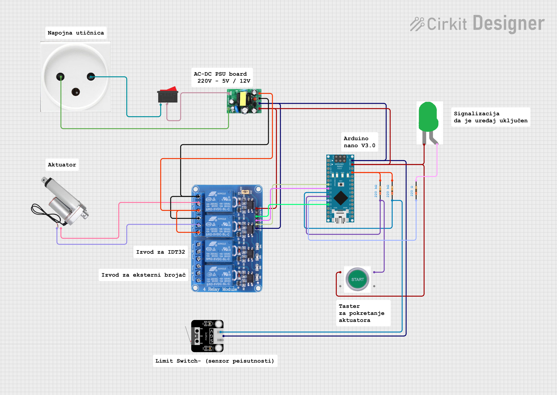
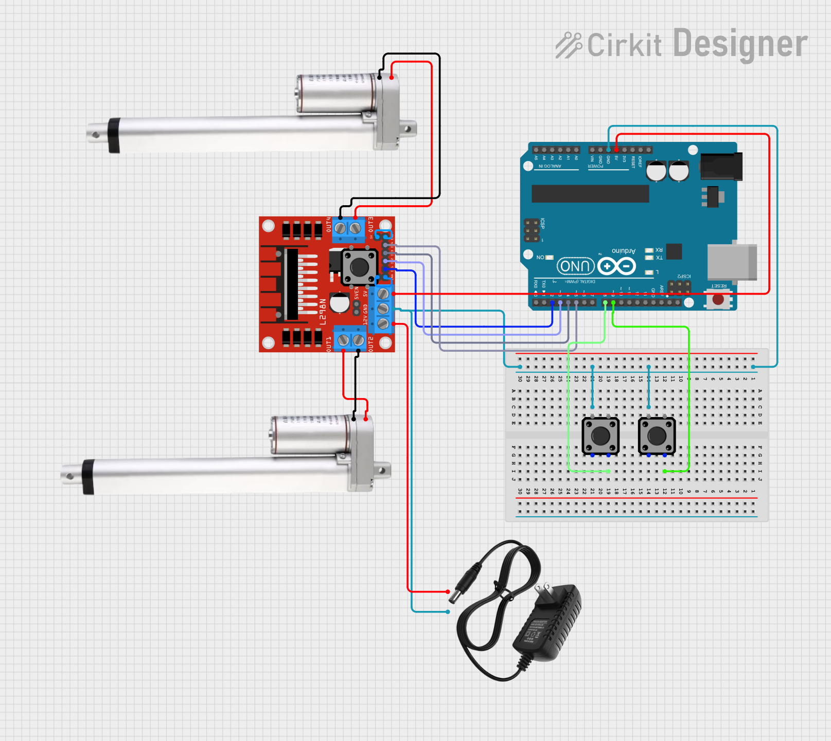
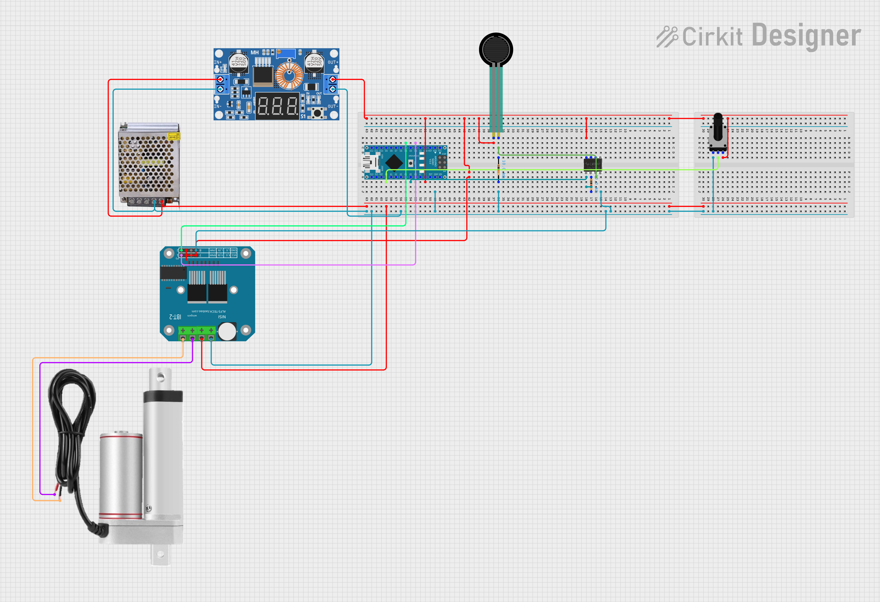
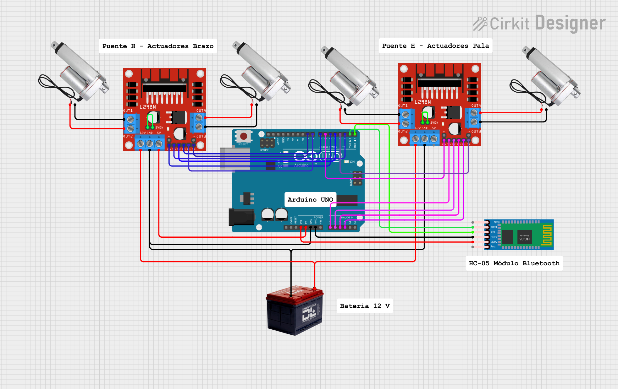
Explore Projects Built with Linear Actuator
Common Applications and Use Cases
- Automation Systems: Used in conveyor belts, sorting machines, and assembly lines.
- Robotics: Enables robotic arms and grippers to perform linear movements.
- Medical Devices: Found in hospital beds, patient lifts, and surgical equipment.
- Home Automation: Used in motorized furniture, window openers, and smart appliances.
- Automotive Systems: Controls seat adjustments, throttle systems, and more.
Technical Specifications
Below are the general technical specifications for a standard linear actuator. Note that specific models may vary, so always refer to the manufacturer's datasheet for exact details.
Key Technical Details
- Input Voltage: 12V DC or 24V DC (common variants)
- Stroke Length: 50mm to 300mm (varies by model)
- Load Capacity: 10kg to 1000kg (depending on the actuator type)
- Speed: 5mm/s to 50mm/s (varies with load and voltage)
- Duty Cycle: 25% (e.g., 1 minute of operation followed by 3 minutes of rest)
- Control Signal: PWM or limit switch-based control
- Operating Temperature: -20°C to 65°C
- Ingress Protection (IP) Rating: IP54 to IP67 (depending on the model)
Pin Configuration and Descriptions
Linear actuators typically have two or more wires for power and control. Below is a table describing the common pin/wire configurations:
| Wire Color | Function | Description |
|---|---|---|
| Red | Positive Power Input (+V) | Connect to the positive terminal of the power supply. |
| Black | Negative Power Input (-V) | Connect to the negative terminal of the power supply (ground). |
| Blue | Limit Switch Signal 1 | Indicates the actuator has reached one end of its stroke (optional). |
| Green | Limit Switch Signal 2 | Indicates the actuator has reached the other end of its stroke (optional). |
| Yellow | PWM Control Signal | Used for speed or position control in advanced models (optional). |
Usage Instructions
How to Use the Component in a Circuit
- Power Connection: Connect the red wire to the positive terminal of a 12V or 24V DC power supply, and the black wire to the negative terminal (ground).
- Polarity Control: To reverse the direction of the actuator, swap the connections of the red and black wires.
- Limit Switches: If the actuator has built-in limit switches, they will automatically stop the actuator at the end of its stroke. No additional circuitry is required for this functionality.
- PWM Control (if available): For actuators with PWM control, connect the yellow wire to a PWM-capable pin on a microcontroller (e.g., Arduino) to adjust speed or position.
Important Considerations and Best Practices
- Voltage Compatibility: Ensure the power supply voltage matches the actuator's rated voltage.
- Load Limits: Do not exceed the actuator's specified load capacity to avoid damage.
- Duty Cycle: Operate the actuator within its duty cycle to prevent overheating.
- Mounting: Securely mount the actuator to prevent misalignment or mechanical stress.
- Wiring: Use appropriate wire gauges to handle the current drawn by the actuator.
Example: Controlling a Linear Actuator with Arduino UNO
Below is an example of how to control a linear actuator using an Arduino UNO and a motor driver (e.g., L298N):
// Arduino code to control a linear actuator using an L298N motor driver

// Define motor driver pins
const int IN1 = 9; // Motor driver input 1
const int IN2 = 10; // Motor driver input 2
const int ENA = 11; // Motor driver enable pin (PWM)

// Setup function
void setup() {
  pinMode(IN1, OUTPUT); // Set IN1 as output
  pinMode(IN2, OUTPUT); // Set IN2 as output
  pinMode(ENA, OUTPUT); // Set ENA as output
}

// Function to extend the actuator
void extendActuator() {
  digitalWrite(IN1, HIGH); // Set IN1 high
  digitalWrite(IN2, LOW);  // Set IN2 low
  analogWrite(ENA, 255);   // Set ENA to full speed (PWM value: 255)
}

// Function to retract the actuator
void retractActuator() {
  digitalWrite(IN1, LOW);  // Set IN1 low
  digitalWrite(IN2, HIGH); // Set IN2 high
  analogWrite(ENA, 255);   // Set ENA to full speed (PWM value: 255)
}

// Function to stop the actuator
void stopActuator() {
  digitalWrite(IN1, LOW);  // Set IN1 low
  digitalWrite(IN2, LOW);  // Set IN2 low
  analogWrite(ENA, 0);     // Set ENA to 0 (stop PWM signal)
}

// Loop function
void loop() {
  extendActuator(); // Extend the actuator
  delay(5000);      // Wait for 5 seconds
  stopActuator();   // Stop the actuator
  delay(2000);      // Wait for 2 seconds
  retractActuator(); // Retract the actuator
  delay(5000);      // Wait for 5 seconds
  stopActuator();   // Stop the actuator
  delay(2000);      // Wait for 2 seconds
}
Troubleshooting and FAQs
Common Issues and Solutions
Actuator Does Not Move:
- Cause: Incorrect wiring or insufficient power supply.
- Solution: Verify the wiring and ensure the power supply matches the actuator's voltage and current requirements.
Actuator Moves in One Direction Only:
- Cause: Faulty motor driver or incorrect polarity control.
- Solution: Check the motor driver connections and ensure the control signals are correct.
Actuator Stops Prematurely:
- Cause: Limit switches are triggered or the load exceeds the capacity.
- Solution: Check for obstructions and ensure the load is within the specified range.
Overheating:
- Cause: Exceeding the duty cycle or continuous operation under heavy load.
- Solution: Operate the actuator within its duty cycle and allow sufficient cooling time.
FAQs
Can I use a linear actuator with an AC power supply? No, most linear actuators are designed for DC power. Use a DC power supply or a suitable AC-to-DC converter.
How do I control the speed of a linear actuator? Use a PWM signal to control the speed. Many motor drivers and microcontrollers support PWM output.
What happens if I exceed the actuator's load capacity? Exceeding the load capacity can damage the actuator's motor or mechanical components. Always operate within the specified limits.
Can I use a linear actuator outdoors? Yes, but ensure the actuator has an appropriate IP rating (e.g., IP65 or higher) for protection against dust and water.