How to Use IBT_2: Examples, Pinouts, and Specs
Introduction
The IBT_2, manufactured by YO with the part ID PUENTE H, is an integrated circuit designed for driving motors and controlling power in various applications. It features high efficiency, low heat generation, and robust performance, making it ideal for projects requiring precise motor control. The IBT_2 is commonly used in robotics, electric vehicles, and industrial automation systems.
Explore Projects Built with IBT_2

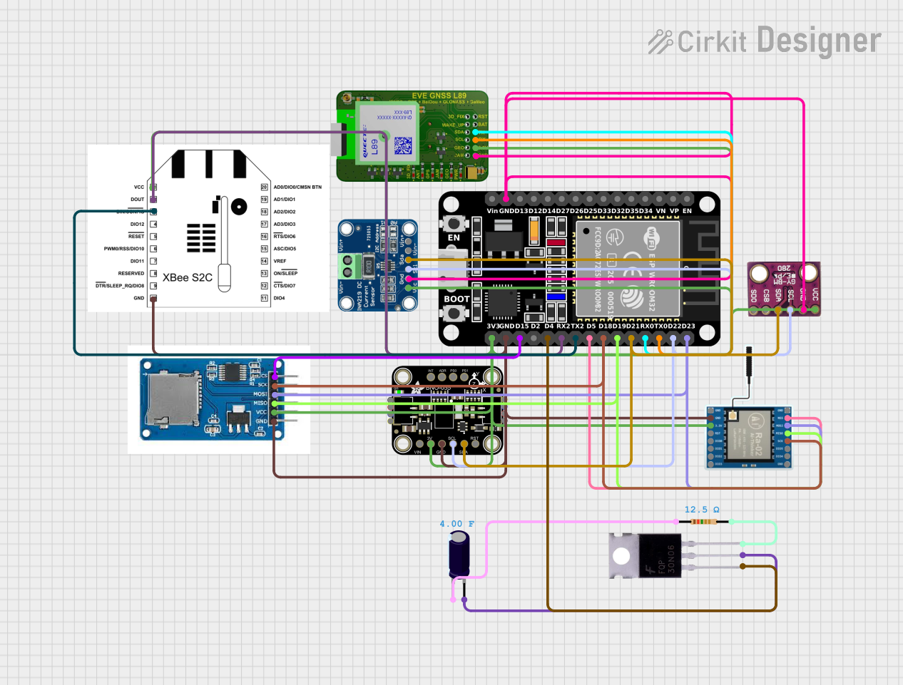
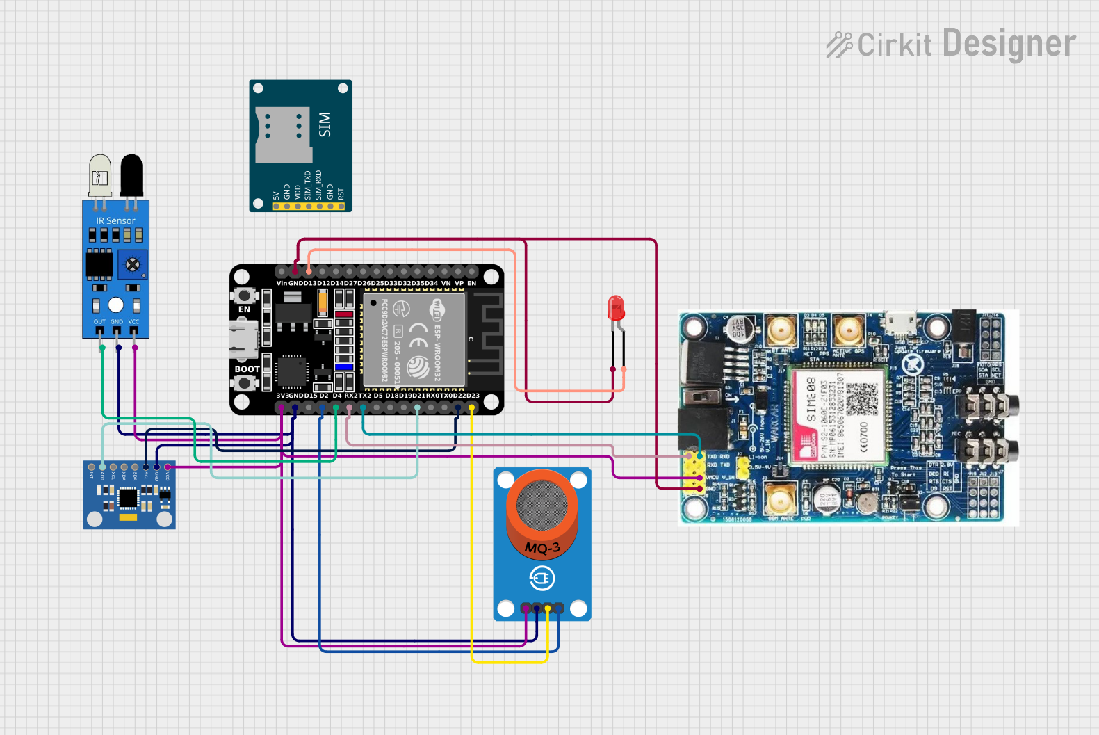
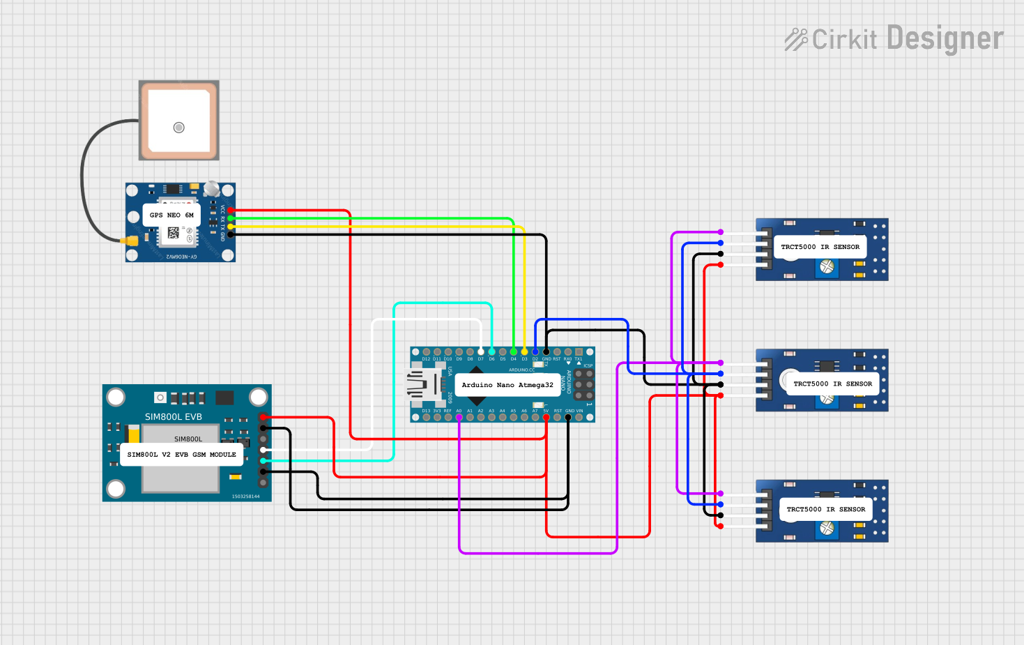
Explore Projects Built with IBT_2
Common Applications
- DC motor control for robotics and automation
- Electric vehicle motor drivers
- Conveyor belt systems
- High-power LED dimming
- Industrial machinery requiring bidirectional motor control
Technical Specifications
Key Technical Details
| Parameter | Value |
|---|---|
| Operating Voltage | 6V to 27V |
| Continuous Current | Up to 43A |
| Peak Current | 100A (short duration) |
| Control Voltage | 3.3V to 5V (logic level) |
| PWM Frequency | Up to 25kHz |
| Efficiency | High (low heat generation) |
| Dimensions | 60mm x 55mm x 30mm |
| Operating Temperature | -25°C to +85°C |
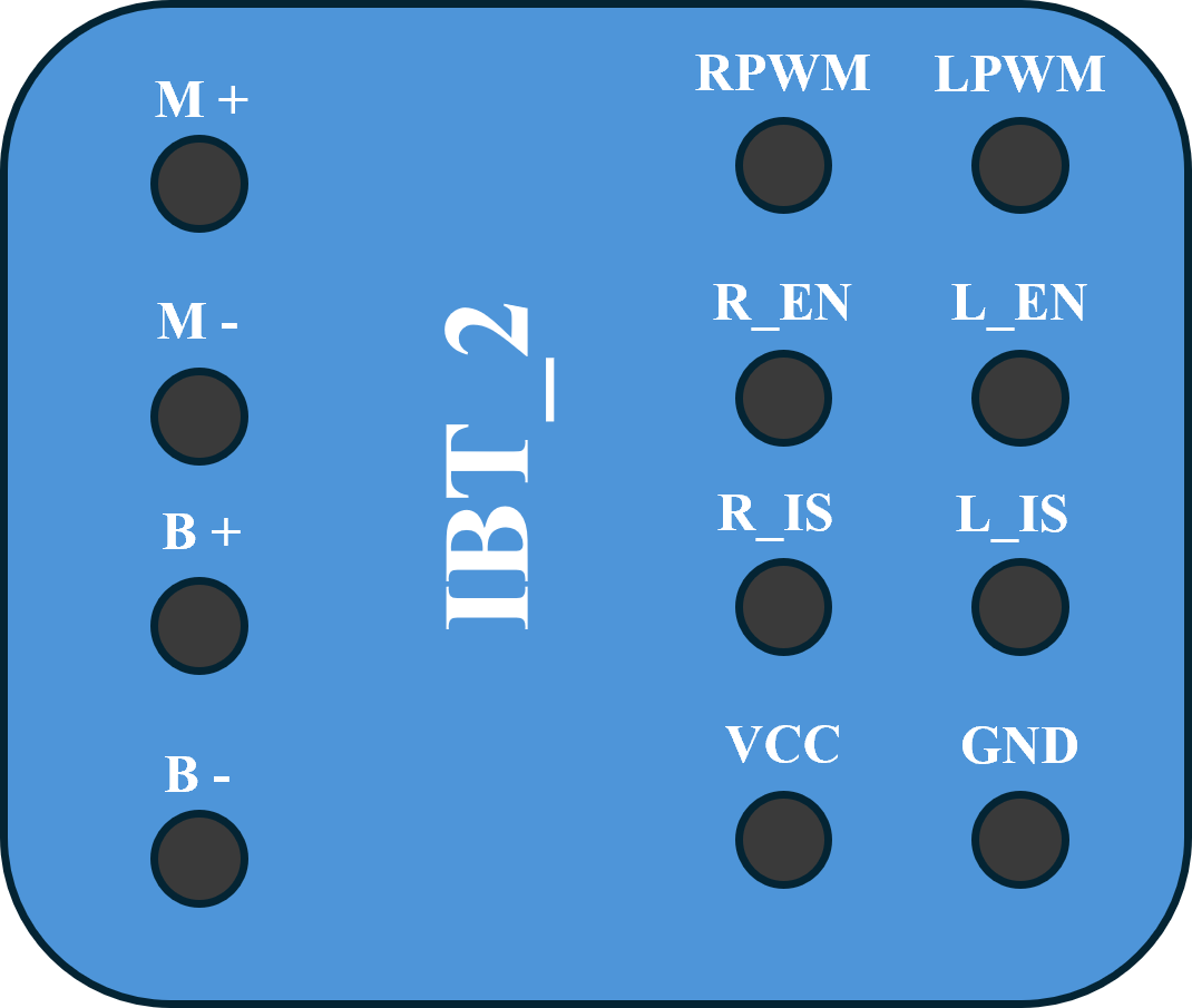
Pin Configuration and Descriptions
The IBT_2 module has a total of 8 pins for control and power connections. Below is the pinout description:
| Pin Number | Pin Name | Description |
|---|---|---|
| 1 | VCC | Logic voltage input (3.3V to 5V) |
| 2 | GND | Ground connection for logic and power |
| 3 | INA | Input A: Controls motor direction (logic HIGH or LOW) |
| 4 | INB | Input B: Controls motor direction (logic HIGH or LOW) |
| 5 | PWM | Pulse Width Modulation input for speed control (3.3V or 5V logic) |
| 6 | EN | Enable pin: Activates the motor driver when HIGH |
| 7 | VM+ | Motor power supply positive terminal (6V to 27V) |
| 8 | VM- | Motor power supply negative terminal (connect to ground) |
Usage Instructions
How to Use the IBT_2 in a Circuit
Power Connections:
- Connect the motor power supply to the
VM+andVM-pins. Ensure the voltage is within the range of 6V to 27V. - Connect the logic power supply (3.3V or 5V) to the
VCCpin and ground to theGNDpin.
- Connect the motor power supply to the
Control Connections:
- Use the
INAandINBpins to control the motor's direction:INA = HIGHandINB = LOW: Motor rotates in one direction.INA = LOWandINB = HIGH: Motor rotates in the opposite direction.- Both
INAandINBLOW: Motor stops.
- Connect the
PWMpin to a microcontroller or PWM signal generator to control motor speed. - Set the
ENpin HIGH to enable the motor driver.
- Use the
Motor Connections:
- Connect the motor terminals to the output terminals of the IBT_2 module.
Important Considerations and Best Practices
- Use a heat sink or active cooling if operating at high currents for extended periods.
- Ensure the power supply can handle the peak current requirements of the motor.
- Use appropriate decoupling capacitors near the power supply pins to reduce noise.
- Avoid reversing the polarity of the power supply connections to prevent damage.
Example: Connecting IBT_2 to an Arduino UNO
Below is an example of how to control a motor using the IBT_2 and an Arduino UNO:
Circuit Connections
VCC→ Arduino 5VGND→ Arduino GNDINA→ Arduino Digital Pin 7INB→ Arduino Digital Pin 8PWM→ Arduino Digital Pin 9 (PWM-capable pin)EN→ Arduino Digital Pin 10VM+→ Motor power supply positive terminalVM-→ Motor power supply ground- Motor terminals → IBT_2 motor output terminals
Arduino Code
// Define control pins for IBT_2
const int INA = 7;  // Direction control pin A
const int INB = 8;  // Direction control pin B
const int PWM = 9;  // PWM pin for speed control
const int EN = 10;  // Enable pin

void setup() {
  // Set pin modes
  pinMode(INA, OUTPUT);
  pinMode(INB, OUTPUT);
  pinMode(PWM, OUTPUT);
  pinMode(EN, OUTPUT);

  // Enable the motor driver
  digitalWrite(EN, HIGH);
}

void loop() {
  // Rotate motor in one direction at 50% speed
  digitalWrite(INA, HIGH);
  digitalWrite(INB, LOW);
  analogWrite(PWM, 128);  // 50% duty cycle (128 out of 255)
  delay(2000);            // Run for 2 seconds

  // Stop the motor
  digitalWrite(INA, LOW);
  digitalWrite(INB, LOW);
  analogWrite(PWM, 0);    // Set speed to 0
  delay(1000);            // Wait for 1 second

  // Rotate motor in the opposite direction at full speed
  digitalWrite(INA, LOW);
  digitalWrite(INB, HIGH);
  analogWrite(PWM, 255);  // 100% duty cycle
  delay(2000);            // Run for 2 seconds

  // Stop the motor
  digitalWrite(INA, LOW);
  digitalWrite(INB, LOW);
  analogWrite(PWM, 0);    // Set speed to 0
  delay(1000);            // Wait for 1 second
}
Troubleshooting and FAQs
Common Issues and Solutions
Motor Not Running:
- Verify that the
ENpin is set HIGH. - Check the power supply connections to
VM+andVM-. - Ensure the motor is properly connected to the output terminals.
- Verify that the
Motor Running in the Wrong Direction:
- Swap the logic levels of
INAandINBto reverse the motor direction.
- Swap the logic levels of
Excessive Heat Generation:
- Ensure the current does not exceed the module's continuous current rating.
- Use a heat sink or active cooling for high-current applications.
PWM Signal Not Working:
- Confirm that the
PWMpin is connected to a PWM-capable pin on the microcontroller. - Check the PWM frequency and ensure it is within the supported range (up to 25kHz).
- Confirm that the
FAQs
Q: Can the IBT_2 drive stepper motors?
A: No, the IBT_2 is designed for DC motor control and is not suitable for stepper motors.
Q: What happens if both INA and INB are HIGH?
A: This configuration is not recommended as it may cause the motor to brake abruptly or damage the module.
Q: Can I use the IBT_2 with a 3.3V microcontroller?
A: Yes, the IBT_2 supports logic levels of 3.3V and 5V, making it compatible with most microcontrollers.
Q: Is reverse polarity protection included?
A: No, the IBT_2 does not have built-in reverse polarity protection. Ensure correct power supply connections to avoid damage.