How to Use 4R7 step down multiple outputs: Examples, Pinouts, and Specs
Introduction
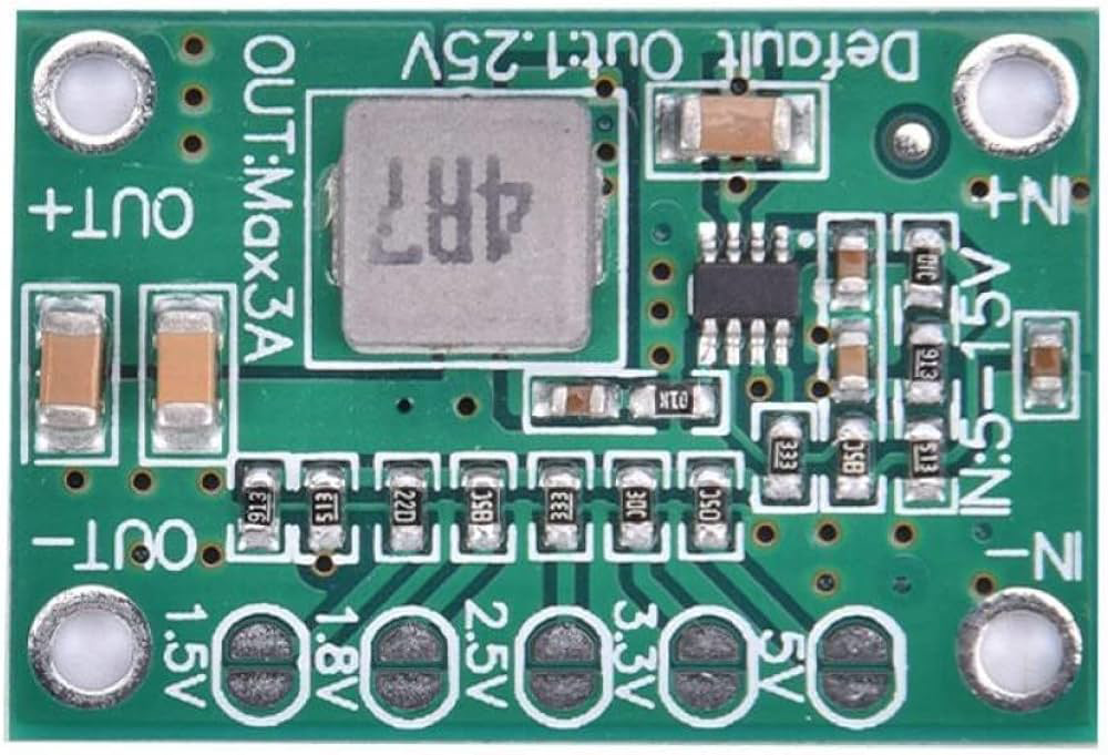
The 4R7 Step Down Multiple Outputs is a transformer or power supply designed to reduce voltage levels while providing multiple output channels. This component is widely used in applications requiring efficient voltage regulation and distribution to multiple devices or circuits. It is particularly suitable for powering microcontrollers, sensors, and other low-voltage electronics from a higher voltage source.
Explore Projects Built with 4R7 step down multiple outputs


Explore Projects Built with 4R7 step down multiple outputs
Common Applications and Use Cases
- Powering microcontrollers (e.g., Arduino, Raspberry Pi) and sensors
- Voltage regulation in embedded systems
- Multi-channel power distribution for electronic devices
- Battery-powered systems requiring step-down voltage conversion
- Industrial and consumer electronics
Technical Specifications
The 4R7 Step Down Multiple Outputs is designed to handle a range of input voltages and provide stable, regulated outputs. Below are the key technical details:
General Specifications
| Parameter | Value |
|---|---|
| Input Voltage Range | 6V to 24V |
| Output Voltage Channels | 3 (e.g., 5V, 3.3V, 12V) |
| Maximum Output Current | 2A per channel (varies by load) |
| Efficiency | Up to 90% |
| Operating Temperature | -20°C to 85°C |
| Dimensions | 40mm x 30mm x 15mm |
Pin Configuration and Descriptions
| Pin Number | Label | Description |
|---|---|---|
| 1 | VIN | Input voltage (6V to 24V) |
| 2 | GND | Ground connection for input and outputs |
| 3 | VOUT1 | Output channel 1 (e.g., 5V) |
| 4 | VOUT2 | Output channel 2 (e.g., 3.3V) |
| 5 | VOUT3 | Output channel 3 (e.g., 12V) |
Usage Instructions
How to Use the 4R7 Step Down Multiple Outputs in a Circuit
Connect the Input Voltage:
- Attach the positive terminal of your power source to the
VINpin. - Connect the negative terminal of your power source to the
GNDpin.
- Attach the positive terminal of your power source to the
Connect the Output Channels:
- Use the
VOUT1,VOUT2, andVOUT3pins to power your devices. - Ensure that the connected devices do not exceed the maximum current rating of 2A per channel.
- Use the
Verify Connections:
- Double-check all connections to avoid short circuits or incorrect wiring.
- Use a multimeter to confirm the output voltages before connecting sensitive devices.
Power On:
- Turn on the power source and monitor the output voltages to ensure proper operation.
Important Considerations and Best Practices
- Heat Dissipation: Ensure adequate ventilation or heat sinking if the component operates near its maximum current rating.
- Load Balancing: Distribute the load evenly across the output channels to prevent overloading a single channel.
- Input Voltage Range: Do not exceed the specified input voltage range (6V to 24V) to avoid damaging the component.
- Capacitor Placement: Place decoupling capacitors near the output pins to reduce noise and improve stability.
Example: Using with an Arduino UNO
The 4R7 Step Down Multiple Outputs can be used to power an Arduino UNO and other peripherals. Below is an example circuit and code:
Circuit Setup
- Connect the
VINpin to a 12V DC power source. - Connect the
VOUT1(5V) pin to the Arduino UNO's5Vpin. - Connect the
GNDpin to the Arduino UNO'sGNDpin.
Arduino Code Example
// Example code to blink an LED using Arduino UNO powered by 4R7 Step Down
// Ensure the 4R7's VOUT1 (5V) is connected to the Arduino's 5V pin.

const int ledPin = 13; // Built-in LED pin on Arduino UNO

void setup() {
  pinMode(ledPin, OUTPUT); // Set the LED pin as an output
}

void loop() {
  digitalWrite(ledPin, HIGH); // Turn the LED on
  delay(1000);                // Wait for 1 second
  digitalWrite(ledPin, LOW);  // Turn the LED off
  delay(1000);                // Wait for 1 second
}
Troubleshooting and FAQs
Common Issues and Solutions
No Output Voltage:
- Cause: Incorrect wiring or insufficient input voltage.
- Solution: Verify the input voltage is within the specified range and check all connections.
Overheating:
- Cause: Excessive current draw or poor ventilation.
- Solution: Reduce the load on the output channels and ensure proper heat dissipation.
Voltage Drop on Outputs:
- Cause: Overloading a single output channel.
- Solution: Distribute the load across multiple channels or reduce the load.
Noise or Instability:
- Cause: Insufficient decoupling or long wires.
- Solution: Add decoupling capacitors near the output pins and shorten wire lengths.
FAQs
Q: Can I use the 4R7 Step Down to power multiple microcontrollers?
A: Yes, as long as the total current draw does not exceed the maximum rating of 2A per channel.Q: What happens if I exceed the input voltage range?
A: Exceeding the input voltage range may damage the component. Always stay within the 6V to 24V range.Q: Can I use only one output channel and leave the others unconnected?
A: Yes, unused output channels can be left unconnected without affecting performance.Q: Is the 4R7 Step Down suitable for battery-powered systems?
A: Yes, it is ideal for battery-powered systems requiring efficient voltage regulation.
By following this documentation, you can effectively integrate the 4R7 Step Down Multiple Outputs into your projects and ensure reliable performance.