
How to Use SparkFun IMU Breakout - MPU-9250: Examples, Pinouts, and Specs

 Design with SparkFun IMU Breakout - MPU-9250 in Cirkit Designer
Introduction
The SparkFun IMU Breakout - MPU-9250 (Manufacturer Part ID: SEN-13762) is a compact and versatile inertial measurement unit (IMU) designed for motion tracking and orientation detection. It integrates a 3-axis accelerometer, 3-axis gyroscope, and 3-axis magnetometer into a single package, making it ideal for applications requiring precise motion sensing and spatial awareness.
Explore Projects Built with SparkFun IMU Breakout - MPU-9250
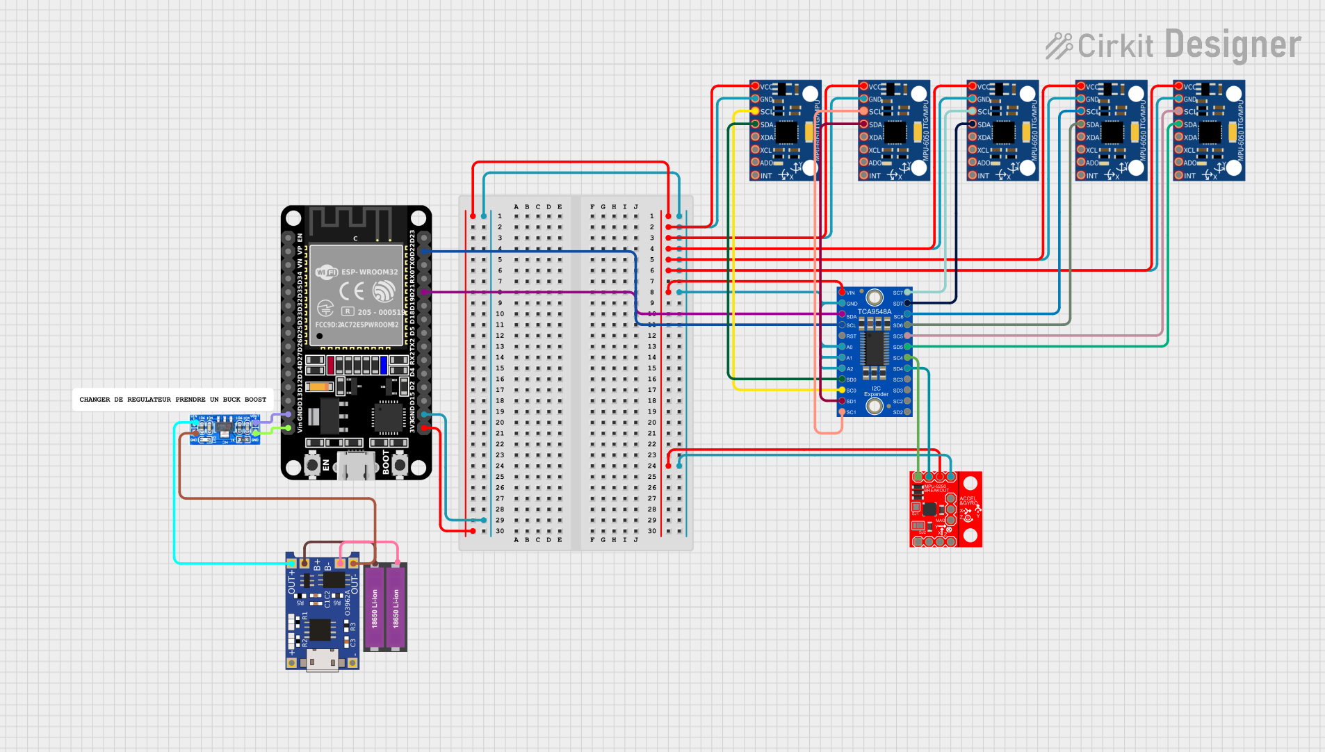 Open Project in Cirkit Designer
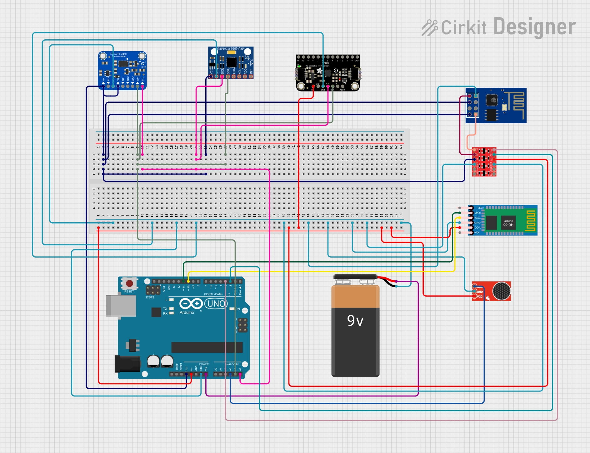 Open Project in Cirkit Designer
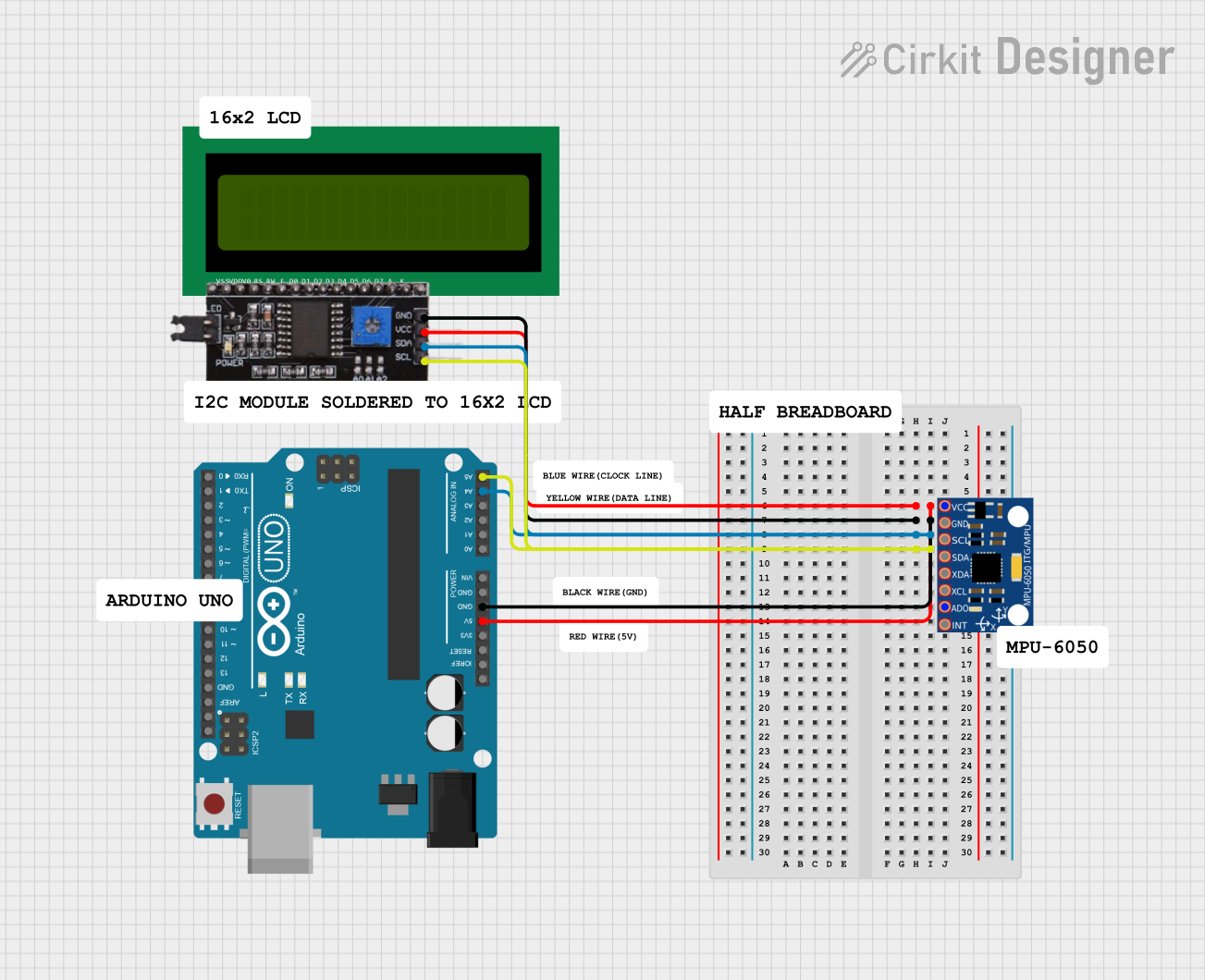 Open Project in Cirkit Designer
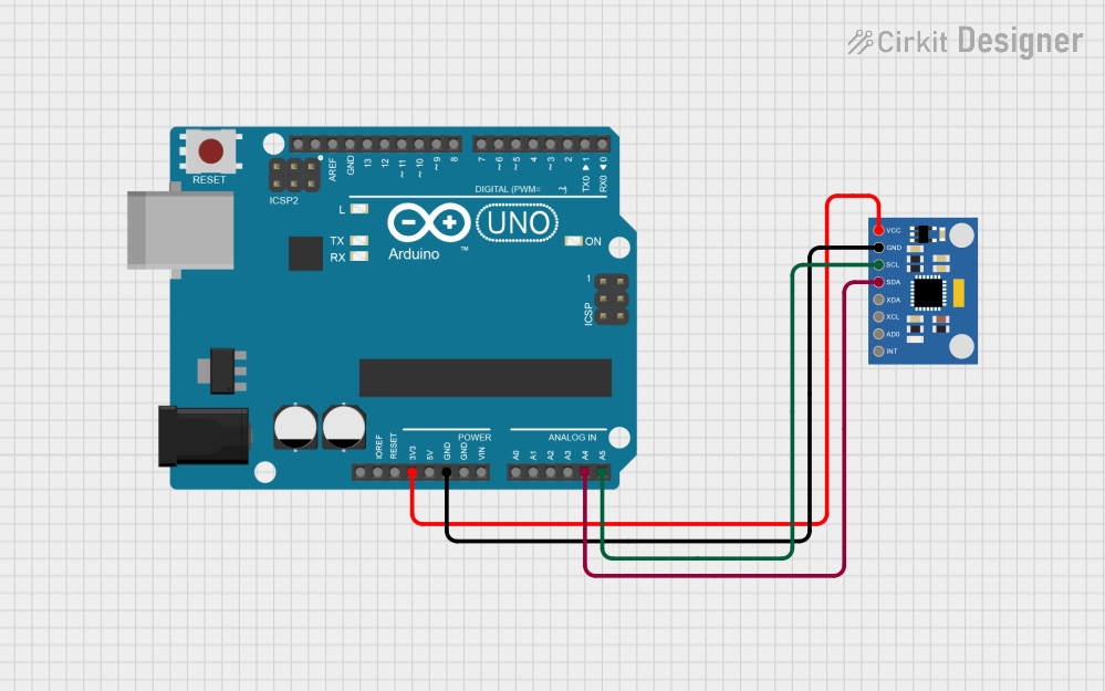 Open Project in Cirkit Designer
Explore Projects Built with SparkFun IMU Breakout - MPU-9250
Open Project in Cirkit DesignerOpen Project in Cirkit DesignerOpen Project in Cirkit DesignerOpen Project in Cirkit DesignerCommon Applications
- Robotics and drone navigation
- Wearable devices and fitness trackers
- Virtual reality (VR) and augmented reality (AR) systems
- Gesture recognition and motion capture
- Automotive and industrial motion sensing
Technical Specifications
The following table outlines the key technical details of the MPU-9250:
| Parameter | Value |
|---|---|
| Supply Voltage | 2.4V to 3.6V (3.3V recommended) |
| Communication Interface | I2C (up to 400kHz) and SPI (up to 1MHz) |
| Accelerometer Range | ±2g, ±4g, ±8g, ±16g (configurable) |
| Gyroscope Range | ±250°/s, ±500°/s, ±1000°/s, ±2000°/s |
| Magnetometer Range | ±4800µT |
| Operating Temperature | -40°C to +85°C |
| Dimensions | 0.8" x 0.8" (20.3mm x 20.3mm) |
Pin Configuration and Descriptions
The MPU-9250 breakout board has the following pin layout:
| Pin | Name | Description |
|---|---|---|
| 1 | GND | Ground |
| 2 | VCC | Power supply (3.3V recommended) |
| 3 | SDA | I2C data line |
| 4 | SCL | I2C clock line |
| 5 | CS | Chip select for SPI communication |
| 6 | SDO | SPI data output |
| 7 | INT | Interrupt pin for motion detection |
| 8 | NCS | Not connected (optional for SPI configuration) |
Usage Instructions
Connecting the MPU-9250 to an Arduino UNO
To use the MPU-9250 with an Arduino UNO, follow these steps:
Wiring:
- Connect the VCC pin of the MPU-9250 to the 3.3V pin on the Arduino.
- Connect the GND pin of the MPU-9250 to the GND pin on the Arduino.
- Connect the SDA pin of the MPU-9250 to the A4 pin on the Arduino (I2C data line).
- Connect the SCL pin of the MPU-9250 to the A5 pin on the Arduino (I2C clock line).
Install Required Libraries:
- Download and install the SparkFun MPU-9250 library from the Arduino Library Manager.
Example Code: Use the following example code to read accelerometer, gyroscope, and magnetometer data:
#include <Wire.h>
#include <SparkFunMPU9250-DMP.h> // Include the SparkFun MPU-9250 library

MPU9250_DMP imu; // Create an instance of the MPU-9250 class

void setup() {
  Serial.begin(115200); // Initialize serial communication
  Wire.begin();         // Initialize I2C communication

  // Initialize the MPU-9250
  if (imu.begin() != INV_SUCCESS) {
    Serial.println("Failed to initialize MPU-9250!");
    while (1); // Halt the program if initialization fails
  }

  Serial.println("MPU-9250 initialized successfully!");
}

void loop() {
  if (imu.dataReady()) { // Check if new data is available
    imu.update();        // Update sensor readings

    // Print accelerometer data
    Serial.print("Accel (g): ");
    Serial.print(imu.calcAccel(imu.ax), 2);
    Serial.print(", ");
    Serial.print(imu.calcAccel(imu.ay), 2);
    Serial.print(", ");
    Serial.println(imu.calcAccel(imu.az), 2);

    // Print gyroscope data
    Serial.print("Gyro (°/s): ");
    Serial.print(imu.calcGyro(imu.gx), 2);
    Serial.print(", ");
    Serial.print(imu.calcGyro(imu.gy), 2);
    Serial.print(", ");
    Serial.println(imu.calcGyro(imu.gz), 2);

    // Print magnetometer data
    Serial.print("Mag (µT): ");
    Serial.print(imu.calcMag(imu.mx), 2);
    Serial.print(", ");
    Serial.print(imu.calcMag(imu.my), 2);
    Serial.print(", ");
    Serial.println(imu.calcMag(imu.mz), 2);

    delay(100); // Delay for readability
  }
}
Important Considerations
- Power Supply: Ensure the MPU-9250 is powered with 3.3V. Supplying 5V may damage the component.
- Pull-Up Resistors: The I2C lines (SDA and SCL) require pull-up resistors. The breakout board includes these resistors, so no additional components are needed.
- Magnetometer Calibration: For accurate magnetometer readings, perform a calibration routine to account for environmental magnetic interference.
Troubleshooting and FAQs
Common Issues
No Data Output:
- Ensure the wiring is correct and matches the pin configuration.
- Verify that the MPU-9250 is powered with 3.3V.
- Check that the I2C address (default: 0x68) is not conflicting with other devices on the bus.
Inaccurate Readings:
- Perform a calibration for the accelerometer, gyroscope, and magnetometer.
- Ensure the breakout board is mounted securely to avoid vibrations.
Library Errors:
- Confirm that the SparkFun MPU-9250 library is installed correctly.
- Update the library to the latest version if issues persist.
FAQs
Q: Can the MPU-9250 be used with a 5V microcontroller?
A: Yes, but you must use a logic level shifter to convert the 5V signals to 3.3V for the MPU-9250.
Q: How do I switch between I2C and SPI communication?
A: By default, the MPU-9250 uses I2C. To use SPI, connect the CS pin to GND and configure the SPI pins accordingly in your code.
Q: What is the maximum sampling rate of the MPU-9250?
A: The maximum sampling rate is 1kHz for the accelerometer and gyroscope, and 100Hz for the magnetometer.