How to Use Digital Compass: Examples, Pinouts, and Specs
Introduction
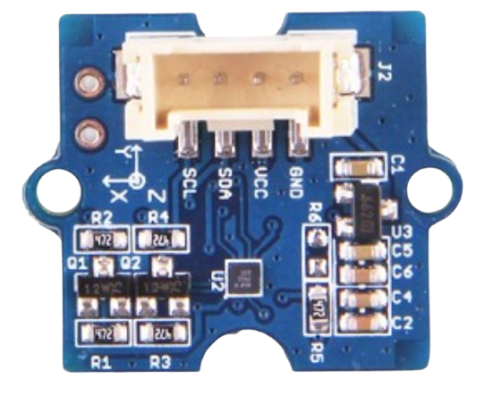
The Grove Digital Compass is an electronic device designed to determine the direction of magnetic north using built-in magnetic field sensors. It provides heading information in degrees, making it an essential component for navigation systems, robotics, and orientation-based applications. The compact design and ease of integration make it suitable for use in smartphones, outdoor equipment, and Arduino-based projects.
Explore Projects Built with Digital Compass


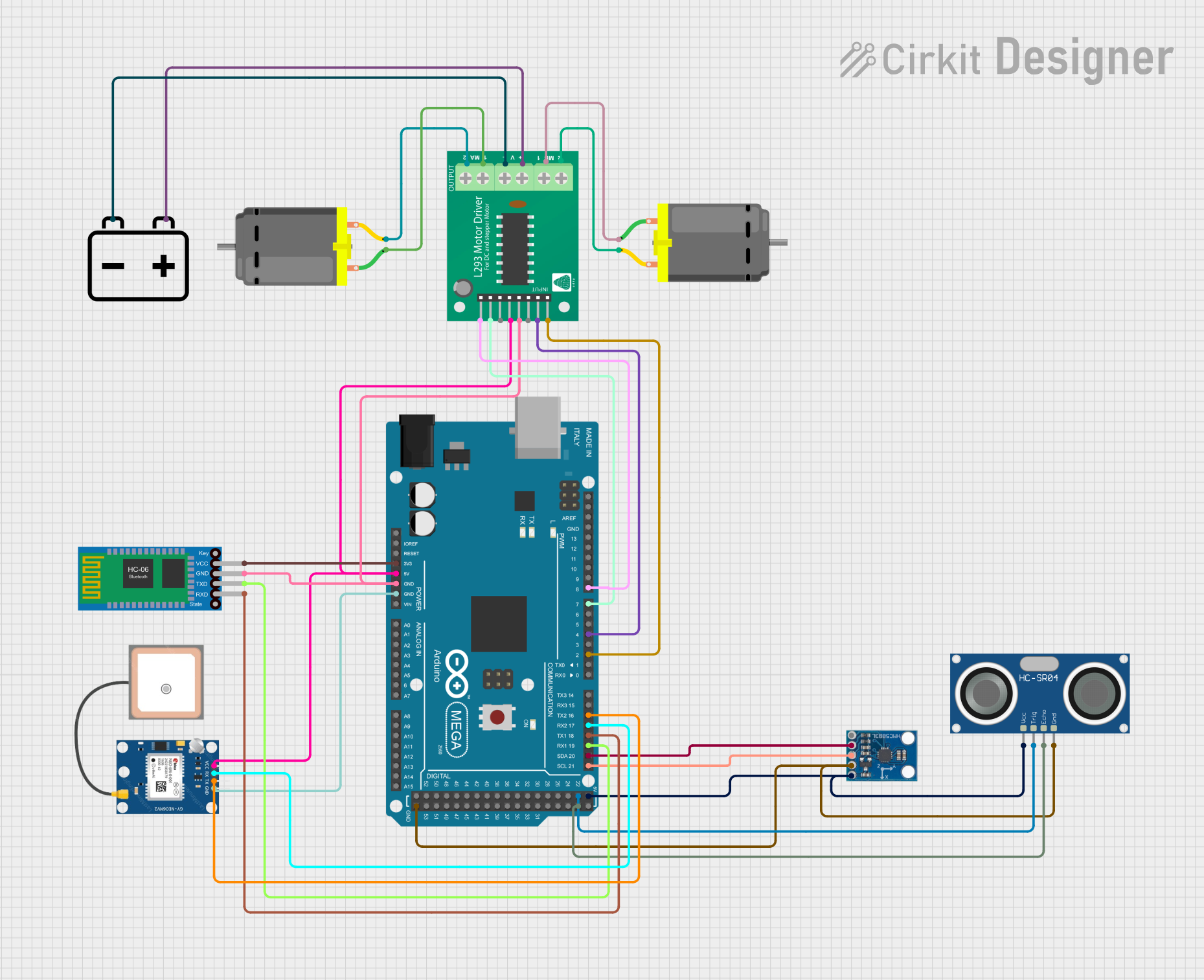
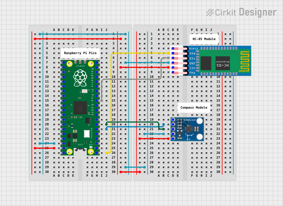
Explore Projects Built with Digital Compass
Common Applications and Use Cases
- Navigation systems for vehicles and drones
- Robotics for orientation and pathfinding
- Wearable devices and outdoor equipment
- Educational projects and prototyping
- Smartphone and tablet orientation sensing
Technical Specifications
The following table outlines the key technical details of the Grove Digital Compass:
| Parameter | Value |
|---|---|
| Operating Voltage | 3.3V to 5V |
| Operating Current | < 10mA |
| Communication Protocol | I2C |
| Measurement Range | 0° to 360° |
| Accuracy | ±1° to ±2° |
| Dimensions | 20mm x 20mm |
| Operating Temperature | -40°C to 85°C |
Pin Configuration and Descriptions
The Grove Digital Compass uses a standard Grove 4-pin interface. The pin configuration is as follows:
| Pin | Name | Description |
|---|---|---|
| 1 | VCC | Power supply pin (3.3V to 5V) |
| 2 | GND | Ground pin |
| 3 | SDA | I2C data line for communication |
| 4 | SCL | I2C clock line for communication |
Usage Instructions
How to Use the Component in a Circuit
Connect the Grove Digital Compass to a Microcontroller:
- Use a Grove Base Shield or directly connect the pins to the microcontroller.
- Ensure the VCC and GND pins are connected to the appropriate power supply and ground.
- Connect the SDA and SCL pins to the corresponding I2C pins on the microcontroller.
Install Required Libraries:
- For Arduino, install the
Wirelibrary (pre-installed in most Arduino IDE setups). - If using a specific Grove library, download and install it from the official Grove documentation or GitHub repository.
- For Arduino, install the
Write and Upload Code:
- Use the provided example code below to read heading data from the compass.
Example Code for Arduino UNO
#include <Wire.h> // Include the Wire library for I2C communication

#define COMPASS_ADDRESS 0x1E // Default I2C address for the Grove Digital Compass

void setup() {
  Serial.begin(9600); // Initialize serial communication at 9600 baud
  Wire.begin();       // Initialize I2C communication
  initializeCompass(); // Call function to configure the compass
}

void loop() {
  int heading = readHeading(); // Read the heading from the compass
  Serial.print("Heading: ");
  Serial.print(heading);
  Serial.println("°"); // Print the heading in degrees
  delay(500); // Wait for 500ms before the next reading
}

void initializeCompass() {
  Wire.beginTransmission(COMPASS_ADDRESS); // Start communication with the compass
  Wire.write(0x00); // Select configuration register A
  Wire.write(0x70); // Set measurement mode to normal
  Wire.endTransmission();

  Wire.beginTransmission(COMPASS_ADDRESS);
  Wire.write(0x01); // Select configuration register B
  Wire.write(0xA0); // Set gain
  Wire.endTransmission();

  Wire.beginTransmission(COMPASS_ADDRESS);
  Wire.write(0x02); // Select mode register
  Wire.write(0x00); // Set continuous measurement mode
  Wire.endTransmission();
}

int readHeading() {
  Wire.beginTransmission(COMPASS_ADDRESS);
  Wire.write(0x03); // Select data output register
  Wire.endTransmission();

  Wire.requestFrom(COMPASS_ADDRESS, 6); // Request 6 bytes of data
  if (Wire.available() == 6) {
    int x = Wire.read() << 8 | Wire.read(); // Read X-axis data
    int z = Wire.read() << 8 | Wire.read(); // Read Z-axis data
    int y = Wire.read() << 8 | Wire.read(); // Read Y-axis data

    // Calculate heading in degrees
    float heading = atan2((float)y, (float)x) * 180 / PI;
    if (heading < 0) heading += 360; // Ensure heading is positive
    return (int)heading;
  }
  return -1; // Return -1 if data is not available
}
Important Considerations and Best Practices
- Avoid Magnetic Interference: Keep the compass away from strong magnetic fields or ferromagnetic materials, as they can distort readings.
- Calibrate the Compass: Perform a calibration routine to improve accuracy, especially in environments with magnetic interference.
- Power Supply Stability: Ensure a stable power supply to avoid fluctuations in readings.
- I2C Address Conflicts: If using multiple I2C devices, ensure they have unique addresses or use an I2C multiplexer.
Troubleshooting and FAQs
Common Issues and Solutions
No Data or Incorrect Readings:
- Ensure the SDA and SCL pins are correctly connected to the microcontroller.
- Verify the I2C address of the compass matches the code (default:
0x1E).
Fluctuating or Inaccurate Readings:
- Check for nearby magnetic interference and move the compass to a different location.
- Perform a calibration routine to improve accuracy.
Device Not Detected:
- Use an I2C scanner sketch to confirm the compass is detected on the I2C bus.
- Ensure the power supply voltage is within the specified range (3.3V to 5V).
FAQs
Q: Can the Grove Digital Compass be used with Raspberry Pi?
A: Yes, the compass can be used with Raspberry Pi via the I2C interface. Use libraries like smbus in Python for communication.
Q: How do I calibrate the compass?
A: Calibration typically involves rotating the compass in all directions to map the magnetic field. Refer to the Grove documentation for specific calibration routines.
Q: What is the maximum range of the compass?
A: The compass provides a full 360° heading range with an accuracy of ±1° to ±2°.
By following this documentation, you can effectively integrate and use the Grove Digital Compass in your projects.