How to Use DC-DC Buck Converter Charging Module: Examples, Pinouts, and Specs
Introduction
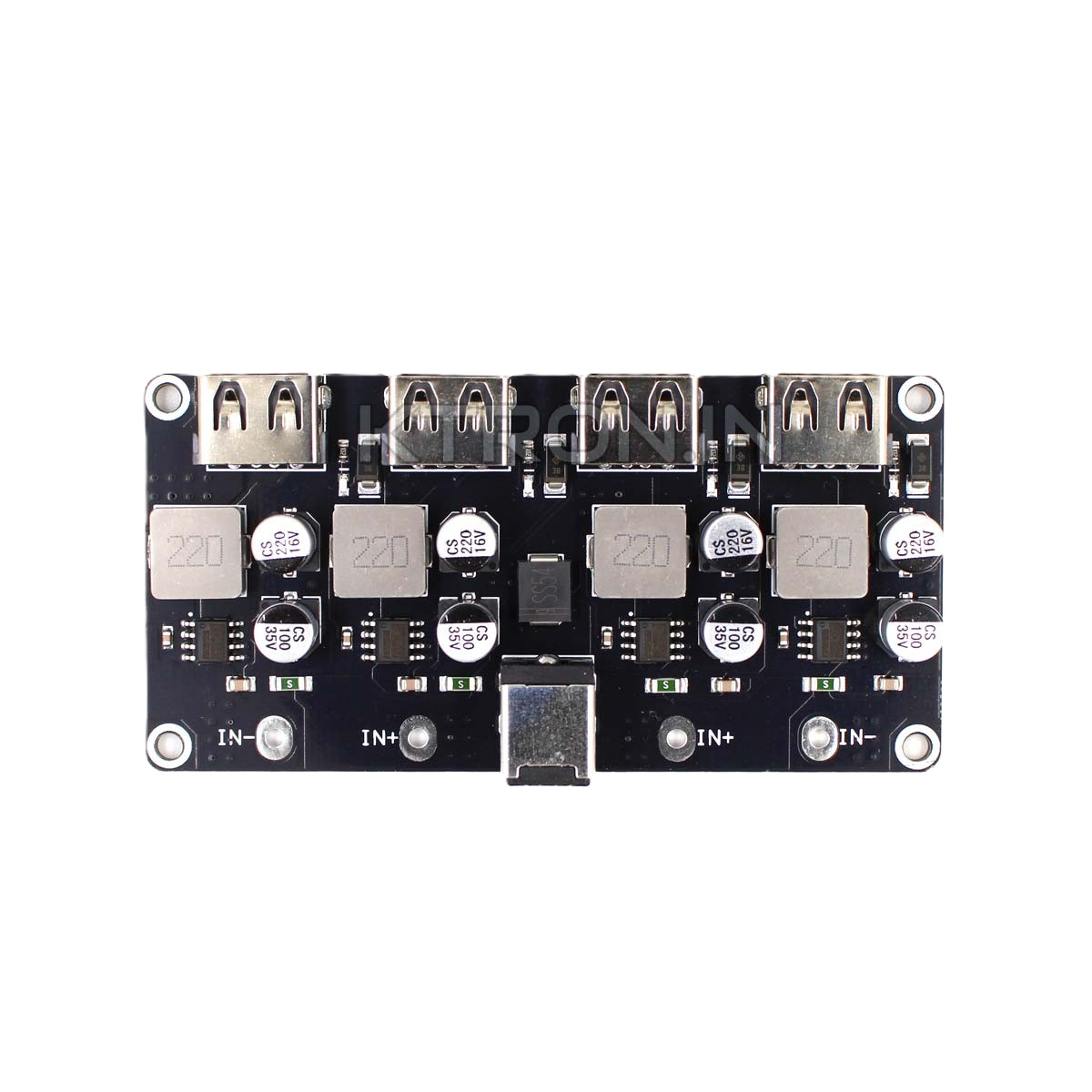
A DC-DC Buck Converter Charging Module is a power management device designed to step down voltage from a higher input level to a lower output level while maintaining high efficiency. This module is widely used in battery charging applications, where it converts a higher input voltage (e.g., from a solar panel, USB power source, or adapter) to a suitable output voltage for charging batteries. Its compact size, efficiency, and versatility make it an essential component in portable electronics, renewable energy systems, and embedded projects.
Explore Projects Built with DC-DC Buck Converter Charging Module


Explore Projects Built with DC-DC Buck Converter Charging Module
Common Applications
- Charging lithium-ion or lithium-polymer batteries
- Powering low-voltage devices from higher-voltage sources
- Renewable energy systems (e.g., solar-powered battery chargers)
- Voltage regulation in embedded systems
- DIY electronics projects
Technical Specifications
Below are the key technical details of a typical DC-DC Buck Converter Charging Module:
| Parameter | Specification |
|---|---|
| Input Voltage Range | 4.5V to 28V |
| Output Voltage Range | Adjustable (e.g., 1.25V to 26V) |
| Output Current | Up to 3A (varies by module) |
| Efficiency | Up to 92% |
| Switching Frequency | 150 kHz |
| Voltage Regulation | ±0.5% |
| Load Regulation | ±0.5% |
| Dimensions | Typically 22mm x 17mm x 4mm |
| Operating Temperature | -40°C to +85°C |
Pin Configuration and Descriptions
The module typically has the following pins or terminals:
| Pin/Terminal | Description |
|---|---|
| VIN | Input voltage terminal (connect to power source) |
| GND | Ground terminal (common ground) |
| VOUT | Output voltage terminal (connect to load/battery) |
| ADJ (optional) | Adjustment pin for setting output voltage |
Usage Instructions
How to Use the Module in a Circuit
Connect the Input Voltage:
- Connect the positive terminal of your power source to the
VINpin. - Connect the negative terminal of your power source to the
GNDpin.
- Connect the positive terminal of your power source to the
Set the Output Voltage:
- If the module has an adjustable output, use the onboard potentiometer to set the desired output voltage.
- Use a multimeter to measure the output voltage at the
VOUTpin while adjusting the potentiometer.
Connect the Load or Battery:
- Connect the positive terminal of your load or battery to the
VOUTpin. - Connect the negative terminal of your load or battery to the
GNDpin.
- Connect the positive terminal of your load or battery to the
Power On:
- Turn on the power source and verify that the output voltage matches the desired level.
Important Considerations and Best Practices
- Input Voltage: Ensure the input voltage is within the specified range (e.g., 4.5V to 28V). Exceeding this range may damage the module.
- Output Current: Do not exceed the maximum output current rating of the module. Use a heatsink if the module gets too hot during operation.
- Voltage Adjustment: When adjusting the output voltage, ensure the load is disconnected to avoid overvoltage damage.
- Polarity: Double-check the polarity of all connections to prevent damage to the module or connected devices.
- Battery Charging: When using the module for battery charging, ensure the output voltage matches the battery's charging requirements.
Example: Using the Module with an Arduino UNO
The DC-DC Buck Converter Charging Module can be used to power an Arduino UNO from a higher voltage source. Below is an example:
- Connect a 12V power source to the
VINandGNDpins of the module. - Adjust the output voltage to 5V using the potentiometer.
- Connect the
VOUTpin to the Arduino's 5V pin and theGNDpin to the Arduino's GND pin.
Here is a simple Arduino sketch to blink an LED while powered by the module:
// Blink an LED connected to pin 13
// Ensure the DC-DC Buck Converter is set to output 5V for the Arduino UNO

void setup() {
  pinMode(13, OUTPUT); // Set pin 13 as an output
}

void loop() {
  digitalWrite(13, HIGH); // Turn the LED on
  delay(1000);            // Wait for 1 second
  digitalWrite(13, LOW);  // Turn the LED off
  delay(1000);            // Wait for 1 second
}
Troubleshooting and FAQs
Common Issues and Solutions
No Output Voltage:
- Check the input voltage and ensure it is within the specified range.
- Verify all connections, especially the polarity of the input and output terminals.
- Ensure the potentiometer is not set to the minimum output voltage.
Overheating:
- Ensure the module is not overloaded. Reduce the load current if necessary.
- Add a heatsink or improve ventilation around the module.
Output Voltage Fluctuations:
- Check for loose connections or poor solder joints.
- Ensure the input voltage is stable and within the specified range.
Battery Not Charging:
- Verify that the output voltage matches the battery's charging requirements.
- Check the battery's polarity and connections.
FAQs
Q: Can this module charge a 3.7V lithium-ion battery?
A: Yes, but you must adjust the output voltage to 4.2V (the full charge voltage for a 3.7V lithium-ion battery).
Q: Can I use this module with a solar panel?
A: Yes, as long as the solar panel's output voltage is within the module's input voltage range.
Q: What happens if I exceed the maximum input voltage?
A: Exceeding the input voltage range may permanently damage the module. Always use a power source within the specified range.
Q: Is the module safe for long-term use?
A: Yes, as long as it is operated within its specifications and proper cooling is provided if necessary.