How to Use Single Socket: Examples, Pinouts, and Specs
Introduction
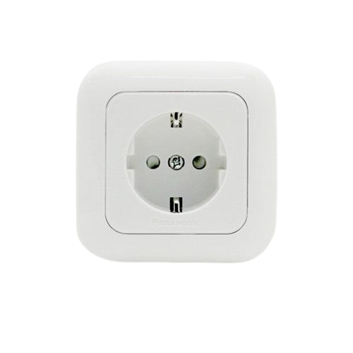
A single socket is an electrical outlet designed to connect one device to the power supply, allowing for the safe and convenient use of electrical appliances. It is a fundamental component in residential, commercial, and industrial electrical systems. Single sockets are typically mounted on walls or panels and are available in various designs to suit different voltage and current requirements.
Explore Projects Built with Single Socket
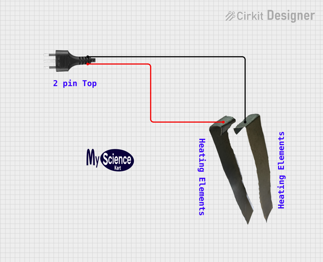

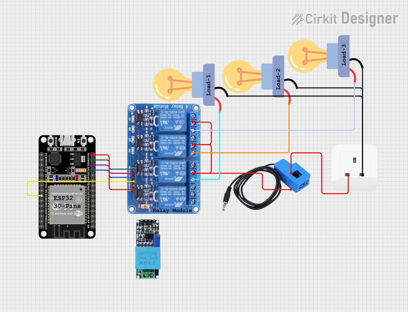

Explore Projects Built with Single Socket
Common Applications and Use Cases
- Powering household appliances such as lamps, chargers, and small kitchen devices.
- Providing power to office equipment like computers and printers.
- Industrial use for connecting tools and machinery with lower power requirements.
- Temporary power supply in construction sites or outdoor events.
Technical Specifications
Key Technical Details
| Parameter | Specification |
|---|---|
| Voltage Rating | 110V - 250V AC (varies by region) |
| Current Rating | 6A - 16A (depending on the model) |
| Frequency | 50Hz / 60Hz |
| Material | Flame-retardant plastic, copper alloy |
| Mounting Type | Wall-mounted or panel-mounted |
| Number of Outlets | 1 |
| Safety Features | Childproof shutters, grounding pin |
Pin Configuration and Descriptions
| Pin Name | Description |
|---|---|
| Line (L) | The live wire connection that carries the current to the device. |
| Neutral (N) | The neutral wire connection that completes the circuit. |
| Ground (G) | The grounding pin for safety, preventing electric shocks and short circuits. |
Usage Instructions
How to Use the Component in a Circuit
- Turn Off Power: Before installation, ensure the main power supply is turned off to avoid electric shock.
- Prepare the Wires: Strip the insulation from the live (L), neutral (N), and ground (G) wires.
- Connect the Wires:
- Attach the live wire to the terminal labeled "L."
- Connect the neutral wire to the terminal labeled "N."
- Secure the ground wire to the terminal labeled "G."
- Secure the Socket: Mount the socket onto the wall or panel using screws.
- Test the Connection: Turn the power back on and test the socket with a device to ensure proper functionality.
Important Considerations and Best Practices
- Always use a socket rated for the voltage and current of your electrical system.
- Ensure proper grounding to prevent electrical hazards.
- Avoid overloading the socket by connecting devices that exceed its current rating.
- Use insulated tools during installation to minimize the risk of electric shock.
- Regularly inspect the socket for signs of wear, damage, or overheating.
Example: Connecting a Single Socket to an Arduino UNO
While single sockets are not directly connected to microcontrollers like the Arduino UNO, they can be used in conjunction with a relay module to control AC devices. Below is an example of how to use a relay module to control a device connected to a single socket.
/*
  Example: Controlling a Single Socket with an Arduino UNO and Relay Module
  This code turns an AC device connected to a single socket ON and OFF
  using a relay module. Ensure proper isolation between AC and DC circuits.
*/

const int relayPin = 7; // Pin connected to the relay module

void setup() {
  pinMode(relayPin, OUTPUT); // Set relay pin as output
  digitalWrite(relayPin, LOW); // Ensure relay is off at startup
}

void loop() {
  digitalWrite(relayPin, HIGH); // Turn the relay ON (device ON)
  delay(5000); // Keep the device ON for 5 seconds
  digitalWrite(relayPin, LOW); // Turn the relay OFF (device OFF)
  delay(5000); // Keep the device OFF for 5 seconds
}
Note: Always use a relay module with proper isolation and ensure safe handling of AC circuits.
Troubleshooting and FAQs
Common Issues Users Might Face
Socket Not Providing Power:
- Cause: Loose wiring or improper connections.
- Solution: Check and secure all wire connections to the terminals.
Overheating Socket:
- Cause: Overloading the socket with high-power devices.
- Solution: Use devices within the socket's current rating and avoid daisy-chaining multiple devices.
Device Not Turning On:
- Cause: Faulty wiring or a tripped circuit breaker.
- Solution: Inspect the wiring and reset the circuit breaker if necessary.
Sparks or Burning Smell:
- Cause: Damaged socket or exposed wires.
- Solution: Immediately turn off the power and replace the socket.
Solutions and Tips for Troubleshooting
- Use a multimeter to check for continuity and proper voltage at the socket terminals.
- Ensure the socket is securely mounted and free from dust or debris.
- If using a relay module with an Arduino, verify the relay's connections and ensure the Arduino's power supply is sufficient.
By following these guidelines, you can safely and effectively use a single socket in your electrical projects.