How to Use Photodiode: Examples, Pinouts, and Specs
Introduction
A photodiode is a semiconductor device that operates by converting light into an electrical current. It is sensitive to varying light intensities and is commonly used in light sensing applications, including ambient light sensors, optical communication, and photometry. When light photons are absorbed by the photodiode, they generate electron-hole pairs, leading to a current flow in the external circuit that is proportional to the light intensity.
Explore Projects Built with Photodiode
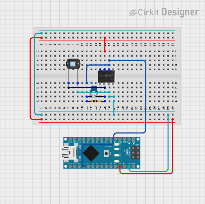
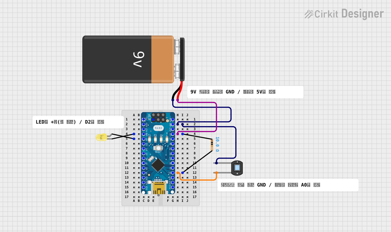
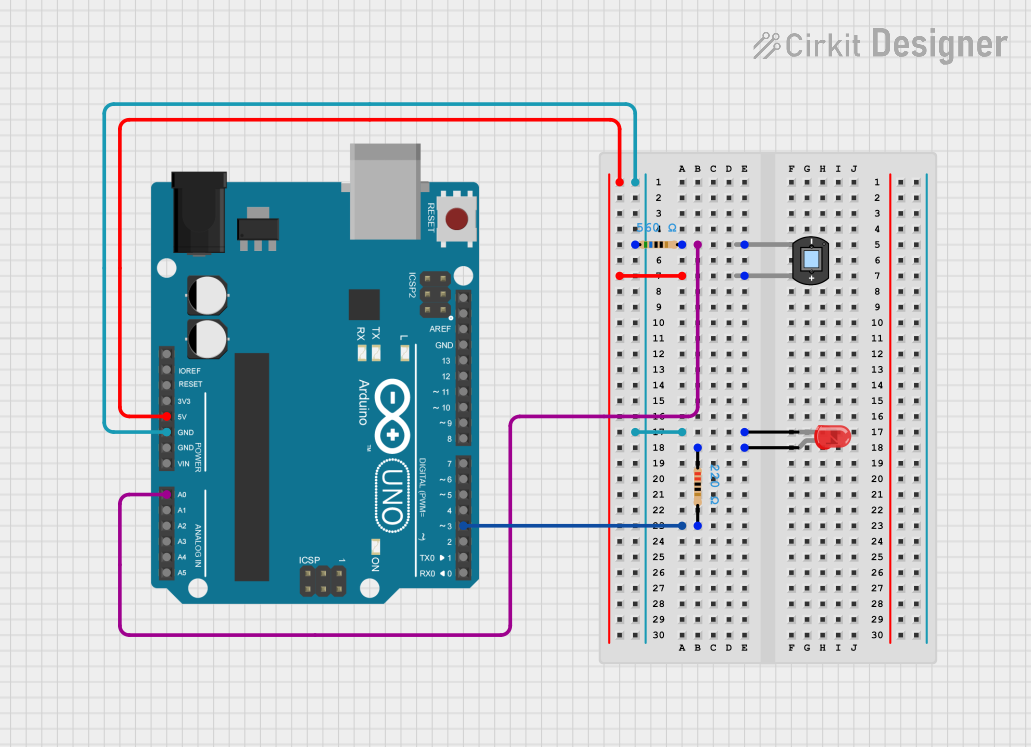
Explore Projects Built with Photodiode
Technical Specifications
Key Technical Details
- Material: Silicon, Germanium, or other semiconductor materials
- Spectral Response: Typically from 200 nm to 1100 nm (varies by material)
- Maximum Reverse Voltage: 5V to 100V (varies by model)
- Dark Current: Typically nA to μA range
- Responsivity: A/W (Ampere per Watt) at a given wavelength
- Capacitance: Typically pF to nF range (varies with reverse bias)
- Package Type: Various (e.g., through-hole, surface-mount, COB)
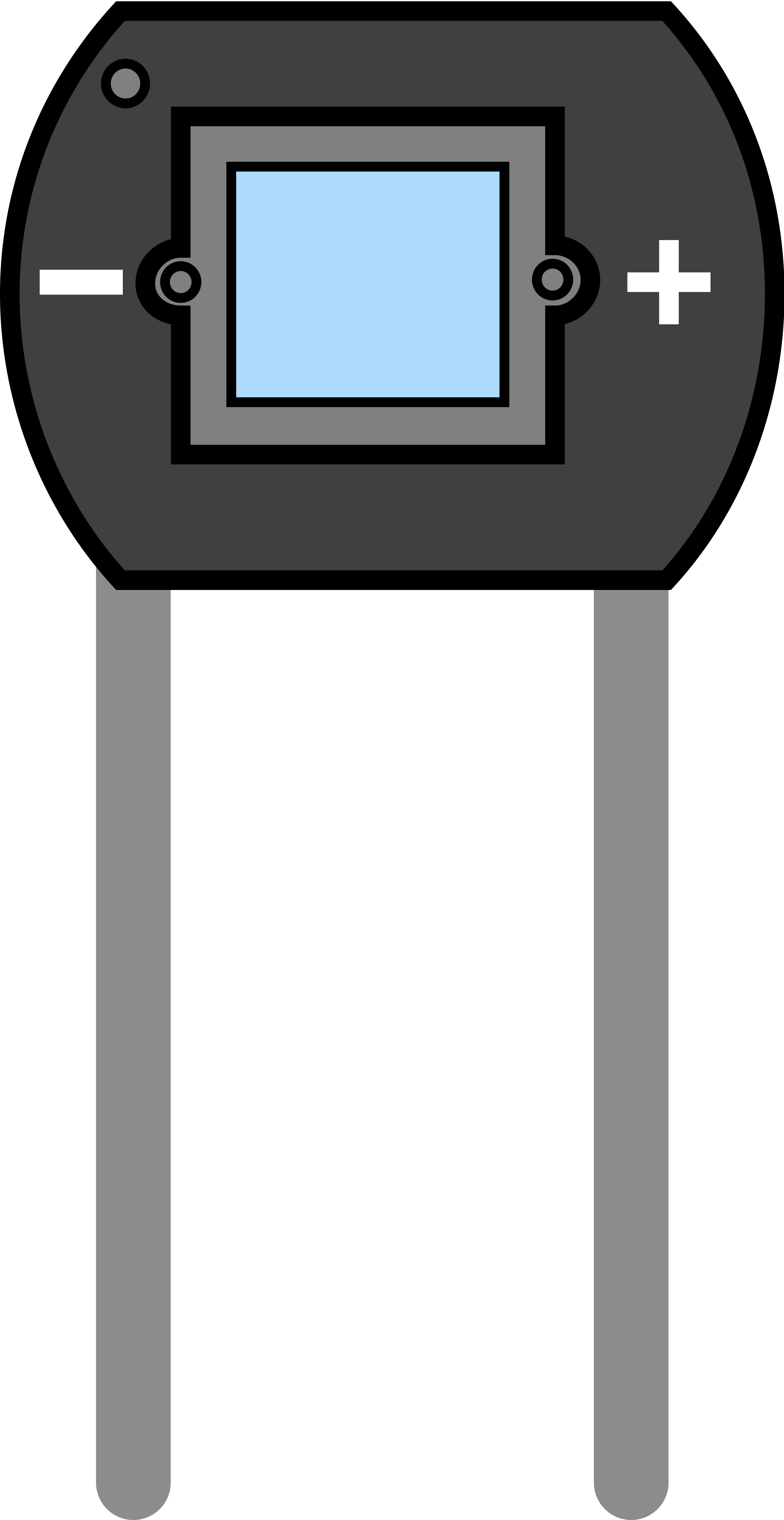
Pin Configuration and Descriptions
| Pin Number | Name | Description |
|---|---|---|
| 1 | Anode | The positive side of the photodiode, typically connected to ground in reverse bias operation. |
| 2 | Cathode | The negative side of the photodiode, where the current is output in reverse bias operation. |
Usage Instructions
Circuit Integration
To use a photodiode in a circuit:
- Connect the anode to the ground.
- Connect the cathode to a positive voltage through a load resistor to measure the photocurrent.
- Choose the load resistor value based on the desired sensitivity and operating voltage.
Best Practices
- Reverse Bias Operation: For faster response times and lower capacitance, operate the photodiode in reverse bias.
- Shielding: To prevent noise, shield the photodiode from stray light and electromagnetic interference.
- Amplification: Use an operational amplifier (op-amp) in a transimpedance configuration to convert the photocurrent to a voltage.
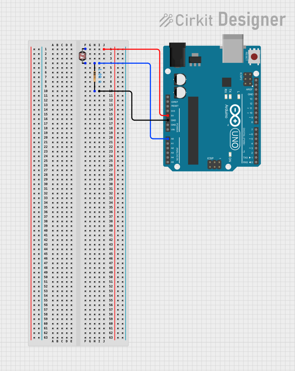
Example Circuit with Arduino UNO
// Photodiode connected to Arduino analog pin A0
const int photodiodePin = A0;
int photocurrent = 0;

void setup() {
  Serial.begin(9600);
}

void loop() {
  photocurrent = analogRead(photodiodePin); // Read the photodiode value
  Serial.println(photocurrent); // Print the value to the Serial Monitor
  delay(200); // Delay for readability
}
Troubleshooting and FAQs
Common Issues
- Low Responsivity: Ensure that the photodiode is correctly biased and the load resistor is properly selected.
- Noise in Signal: Check for proper shielding and grounding. Use a low-noise op-amp for signal amplification.
- Slow Response: Reduce the capacitance by increasing the reverse bias voltage or using a photodiode with lower capacitance.
FAQs
Q: Can I use a photodiode to measure the exact intensity of light? A: Yes, with proper calibration, a photodiode can be used to measure light intensity.
Q: How do I increase the sensitivity of my photodiode circuit? A: Use a larger load resistor or an op-amp in a transimpedance amplifier configuration to increase sensitivity.
Q: What is the difference between a photodiode and a phototransistor? A: A phototransistor is similar to a photodiode but with internal gain, which makes it more sensitive but slower than a photodiode.
Remember to always consult the specific datasheet for your photodiode model for precise specifications and recommendations.