How to Use esp32 s3: Examples, Pinouts, and Specs
Introduction
The ESP32-S3 is a powerful and versatile microcontroller designed for Internet of Things (IoT) applications. It features integrated Wi-Fi and Bluetooth connectivity, a dual-core processor, and enhanced AI capabilities, making it ideal for projects that require wireless communication and significant processing power. The ESP32-S3 is equipped with a variety of peripherals, including GPIOs, ADCs, UARTs, and SPI interfaces, enabling seamless integration into complex systems.
Explore Projects Built with esp32 s3


Explore Projects Built with esp32 s3
Common Applications and Use Cases
- Smart home devices (e.g., smart lights, thermostats, and security systems)
- Wearable technology and health monitoring devices
- Industrial IoT systems for monitoring and automation
- AI and machine learning applications, such as image recognition
- Wireless sensor networks
- Robotics and automation projects
Technical Specifications
The ESP32-S3 offers a robust set of features and specifications that make it suitable for a wide range of applications.
Key Technical Details
| Feature | Specification |
|---|---|
| Processor | Dual-core Xtensa LX7, up to 240 MHz |
| Wireless Connectivity | Wi-Fi 802.11 b/g/n (2.4 GHz), Bluetooth 5.0 LE |
| Flash Memory | Up to 16 MB external flash |
| RAM | 512 KB internal SRAM, support for external PSRAM |
| GPIO Pins | Up to 45 GPIOs (multiplexed with other functions) |
| ADC | 12-bit, up to 20 channels |
| UART | Up to 3 UART interfaces |
| SPI/I2C/I2S | Multiple SPI, I2C, and I2S interfaces |
| PWM | 16 channels |
| Operating Voltage | 3.0V to 3.6V |
| Power Consumption | Ultra-low power modes available |
| AI Capabilities | Vector instructions for AI acceleration |
| Temperature Range | -40°C to +85°C |
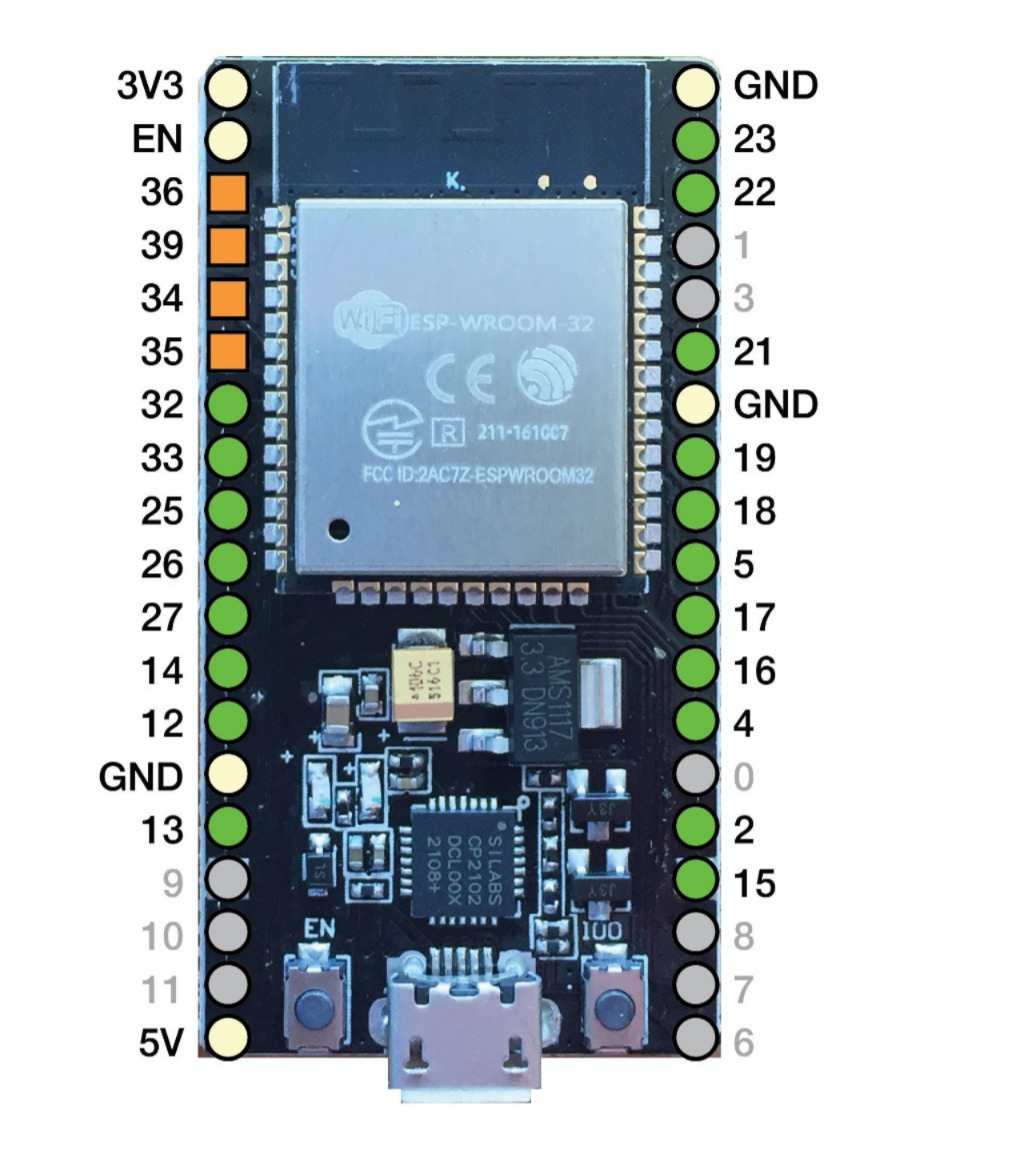
Pin Configuration and Descriptions
The ESP32-S3 has a flexible pin configuration. Below is a table summarizing the key pins and their functions.
| Pin Name | Function | Description |
|---|---|---|
| GPIO0 | Input/Output, Boot Mode Select | Used for boot mode selection during startup |
| GPIO1-45 | General Purpose I/O | Configurable as digital input/output, ADC, or other functions |
| EN | Enable | Resets the chip when pulled low |
| 3V3 | Power Supply | 3.3V power input |
| GND | Ground | Ground connection |
| TXD0/RXD0 | UART0 TX/RX | Default UART for programming and debugging |
| SCL/SDA | I2C Clock/Data | I2C communication interface |
| SPI_CLK | SPI Clock | SPI communication clock |
| SPI_MOSI | SPI Master Out, Slave In | SPI data output from master |
| SPI_MISO | SPI Master In, Slave Out | SPI data input to master |
Usage Instructions
The ESP32-S3 is a versatile microcontroller that can be used in a variety of circuits. Below are the steps and best practices for using the ESP32-S3 in your projects.
How to Use the ESP32-S3 in a Circuit
- Power Supply: Ensure the ESP32-S3 is powered with a stable 3.3V supply. Avoid exceeding the maximum voltage of 3.6V.
- Boot Mode: To upload code, connect GPIO0 to GND and reset the chip. This puts the ESP32-S3 into bootloader mode.
- Programming: Use a USB-to-UART adapter or a development board with built-in USB support to upload code via the UART0 interface.
- Peripherals: Connect sensors, actuators, or other devices to the GPIO pins. Configure the pins in your code as needed (e.g., input, output, ADC).
- Wi-Fi and Bluetooth: Use the built-in libraries (e.g.,
WiFi.handBluetoothSerial.h) to enable wireless communication.
Important Considerations and Best Practices
- Voltage Levels: Ensure all connected devices operate at 3.3V logic levels. Use level shifters if interfacing with 5V devices.
- Decoupling Capacitors: Place decoupling capacitors (e.g., 0.1 µF) near the power pins to reduce noise.
- Antenna Placement: For optimal wireless performance, ensure the onboard antenna is not obstructed by metal or other conductive materials.
- Heat Management: If running intensive tasks, consider adding a heatsink or ensuring proper ventilation to prevent overheating.
Example Code for Arduino IDE
The ESP32-S3 is compatible with the Arduino IDE. Below is an example of how to connect to a Wi-Fi network and blink an LED.
#include <WiFi.h> // Include the Wi-Fi library

const char* ssid = "Your_SSID";       // Replace with your Wi-Fi network name
const char* password = "Your_Password"; // Replace with your Wi-Fi password
const int ledPin = 2;                 // GPIO pin for the onboard LED

void setup() {
  pinMode(ledPin, OUTPUT);            // Set the LED pin as an output
  Serial.begin(115200);               // Start the serial communication
  Serial.println("Connecting to Wi-Fi...");

  WiFi.begin(ssid, password);         // Connect to the Wi-Fi network
  while (WiFi.status() != WL_CONNECTED) {
    delay(500);
    Serial.print(".");                // Print dots while connecting
  }

  Serial.println("\nWi-Fi connected!");
  Serial.print("IP Address: ");
  Serial.println(WiFi.localIP());     // Print the device's IP address
}

void loop() {
  digitalWrite(ledPin, HIGH);         // Turn the LED on
  delay(1000);                        // Wait for 1 second
  digitalWrite(ledPin, LOW);          // Turn the LED off
  delay(1000);                        // Wait for 1 second
}
Troubleshooting and FAQs
Common Issues and Solutions
ESP32-S3 Not Connecting to Wi-Fi
- Solution: Double-check the SSID and password. Ensure the Wi-Fi network is 2.4 GHz, as the ESP32-S3 does not support 5 GHz networks.
Code Upload Fails
- Solution: Ensure GPIO0 is connected to GND during bootloader mode. Verify the correct COM port and board settings in the Arduino IDE.
Unstable Operation or Random Resets
- Solution: Check the power supply for stability. Use a capacitor near the power pins to filter noise.
Bluetooth Not Working
- Solution: Ensure the Bluetooth library is included and initialized correctly. Verify that no other devices are interfering with the connection.
FAQs
Q: Can the ESP32-S3 run on battery power?
- A: Yes, the ESP32-S3 can run on battery power. Use a 3.7V LiPo battery with a voltage regulator to provide 3.3V.
Q: How do I update the firmware?
- A: Use the ESP32-S3's bootloader mode and a tool like
esptool.pyto flash new firmware.
- A: Use the ESP32-S3's bootloader mode and a tool like
Q: Can I use the ESP32-S3 for AI applications?
- A: Yes, the ESP32-S3 includes vector instructions for AI acceleration, making it suitable for lightweight AI tasks like image recognition or speech processing.