Cirkit Designer Logo
Cirkit Designer
Your all-in-one circuit design IDE
Home / 
Component Documentation

How to Use LM2596: Examples, Pinouts, and Specs

Image of LM2596
Cirkit Designer LogoDesign with LM2596 in Cirkit Designer

Introduction

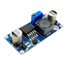
The LM2596 is a versatile step-down (buck) voltage regulator designed to efficiently convert a higher input voltage to a lower, stable output voltage. Capable of driving a 3A load with excellent line and load regulation, the LM2596 is widely used in various applications, including power supply units, battery chargers, and embedded systems.

Explore Projects Built with LM2596

Use Cirkit Designer to design, explore, and prototype these projects online. Some projects support real-time simulation. Click "Open Project" to start designing instantly!
ESP32-Based Solar-Powered Current Monitoring System with OLED Display
Image of Solar Tracker and Monitoring System: A project utilizing LM2596 in a practical application
This circuit features an ESP32 microcontroller interfaced with a 0.96" OLED display, multiple LDR sensors with voltage dividers, an ACS712 current sensor, and two servomotors. The ESP32 reads analog values from the LDRs and the current sensor, and controls the servomotors. The LM2596 module steps down voltage for the circuit, which is powered by a combination of a solar panel and a 12V battery, with the current sensor monitoring the load current.
Cirkit Designer LogoOpen Project in Cirkit Designer
Arduino Nano Based GPS Tracker with GSM Communication and Accelerometer
Image of Circuit Aayush: A project utilizing LM2596 in a practical application
This circuit is designed for communication and location tracking purposes. It features an Arduino Nano interfaced with a SIM800L GSM module for cellular connectivity, a GPS NEO 6M module for obtaining geographical coordinates, and an AITrip ADXL335 GY-61 accelerometer for motion sensing. The LM2596 Step Down Module is used to regulate the power supply to the components.
Cirkit Designer LogoOpen Project in Cirkit Designer
Arduino GSM Security System with Motion Detection and Light Sensing
Image of Smart Home Security: A project utilizing LM2596 in a practical application
This circuit is designed to interface an Arduino UNO with a SIM800L GSM module, PIR sensor, photocell, buzzer, and multiple LEDs. It is likely intended for environmental monitoring and alerting, with the capability to communicate over GSM for remote notifications. The LM2596 module provides voltage regulation for the GSM module.
Cirkit Designer LogoOpen Project in Cirkit Designer
ESP8266 and SIM800L Based GPS Tracker with I2C LCD Display and Battery Power
Image of Little Innovator Competition: A project utilizing LM2596 in a practical application
This circuit integrates an ESP8266 NodeMCU microcontroller with a SIM800L GSM module, a GPS NEO 6M module, and a 16x2 I2C LCD display for communication and location tracking. It also includes a pushbutton for user input, a piezo buzzer for audio alerts, and is powered by a 2x 18650 battery pack through an LM2596 step-down module.
Cirkit Designer LogoOpen Project in Cirkit Designer

Explore Projects Built with LM2596

Use Cirkit Designer to design, explore, and prototype these projects online. Some projects support real-time simulation. Click "Open Project" to start designing instantly!
Image of Solar Tracker and Monitoring System: A project utilizing LM2596 in a practical application
ESP32-Based Solar-Powered Current Monitoring System with OLED Display
This circuit features an ESP32 microcontroller interfaced with a 0.96" OLED display, multiple LDR sensors with voltage dividers, an ACS712 current sensor, and two servomotors. The ESP32 reads analog values from the LDRs and the current sensor, and controls the servomotors. The LM2596 module steps down voltage for the circuit, which is powered by a combination of a solar panel and a 12V battery, with the current sensor monitoring the load current.
Cirkit Designer LogoOpen Project in Cirkit Designer
Image of Circuit Aayush: A project utilizing LM2596 in a practical application
Arduino Nano Based GPS Tracker with GSM Communication and Accelerometer
This circuit is designed for communication and location tracking purposes. It features an Arduino Nano interfaced with a SIM800L GSM module for cellular connectivity, a GPS NEO 6M module for obtaining geographical coordinates, and an AITrip ADXL335 GY-61 accelerometer for motion sensing. The LM2596 Step Down Module is used to regulate the power supply to the components.
Cirkit Designer LogoOpen Project in Cirkit Designer
Image of Smart Home Security: A project utilizing LM2596 in a practical application
Arduino GSM Security System with Motion Detection and Light Sensing
This circuit is designed to interface an Arduino UNO with a SIM800L GSM module, PIR sensor, photocell, buzzer, and multiple LEDs. It is likely intended for environmental monitoring and alerting, with the capability to communicate over GSM for remote notifications. The LM2596 module provides voltage regulation for the GSM module.
Cirkit Designer LogoOpen Project in Cirkit Designer
Image of Little Innovator Competition: A project utilizing LM2596 in a practical application
ESP8266 and SIM800L Based GPS Tracker with I2C LCD Display and Battery Power
This circuit integrates an ESP8266 NodeMCU microcontroller with a SIM800L GSM module, a GPS NEO 6M module, and a 16x2 I2C LCD display for communication and location tracking. It also includes a pushbutton for user input, a piezo buzzer for audio alerts, and is powered by a 2x 18650 battery pack through an LM2596 step-down module.
Cirkit Designer LogoOpen Project in Cirkit Designer

Common Applications and Use Cases

  • Power supply units for electronic devices
  • Battery chargers
  • Voltage regulation in embedded systems
  • DC-DC converters in automotive and industrial applications

Technical Specifications

Key Technical Details

Parameter Value
Input Voltage Range 4.5V to 40V
Output Voltage Range 1.23V to 37V (adjustable)
Output Current Up to 3A
Efficiency Up to 90%
Switching Frequency 150 kHz
Output Voltage Accuracy ±4%
Operating Temperature -40°C to +125°C
Package TO-220, TO-263, and other surface-mount

Pin Configuration and Descriptions

TO-220 Package

Pin Number Pin Name Description
1 VIN Input voltage (4.5V to 40V)
2 VOUT Output voltage (1.23V to 37V)
3 GND Ground
4 FB Feedback pin for output voltage adjustment
5 ON/OFF Enable/disable control (optional)

Usage Instructions

How to Use the LM2596 in a Circuit

  1. Input and Output Capacitors: Connect a suitable input capacitor (e.g., 100µF) between VIN and GND to filter input voltage. Similarly, connect an output capacitor (e.g., 220µF) between VOUT and GND to stabilize the output voltage.
  2. Inductor Selection: Choose an appropriate inductor value (e.g., 33µH) based on the desired output voltage and current.
  3. Feedback Resistors: Use a voltage divider network (two resistors) connected to the FB pin to set the desired output voltage.
  4. Enable Pin: If using the ON/OFF pin, connect it to a logic level signal to enable or disable the regulator.

Important Considerations and Best Practices

  • Ensure proper heat dissipation by using a heatsink if necessary, especially when operating at high currents.
  • Keep the input and output capacitors close to the regulator to minimize noise and improve stability.
  • Use low ESR capacitors for better performance.
  • Follow the recommended PCB layout guidelines to minimize electromagnetic interference (EMI).

Example Circuit Diagram

       +---------+       +---------+
VIN ---| 1     5 |--- EN |         |
       |         |       |         |
GND ---| 3     4 |--- FB | LM2596  |
       |         |       |         |
VOUT --| 2       |       |         |
       +---------+       +---------+

Troubleshooting and FAQs

Common Issues and Solutions

  1. Output Voltage Not Stable

    • Solution: Check the input and output capacitors for proper values and placement. Ensure the feedback resistors are correctly calculated and connected.
  2. Regulator Overheating

    • Solution: Ensure adequate heat dissipation using a heatsink. Verify that the input voltage is within the specified range and that the load current does not exceed 3A.
  3. No Output Voltage

    • Solution: Check the connections, especially the VIN and GND pins. Ensure the ON/OFF pin is properly connected to enable the regulator.

FAQs

Q1: Can the LM2596 be used with an Arduino UNO?

  • A1: Yes, the LM2596 can be used to provide a stable voltage supply to an Arduino UNO. Ensure the output voltage is set to 5V or 3.3V as required by the Arduino.

Q2: How do I calculate the feedback resistors for a specific output voltage?

  • A2: Use the formula ( V_{OUT} = V_{REF} \times (1 + \frac{R1}{R2}) ), where ( V_{REF} ) is 1.23V. Choose R1 and R2 to set the desired output voltage.

Q3: What is the maximum input voltage for the LM2596?

  • A3: The maximum input voltage for the LM2596 is 40V.

Example Arduino Code

// Example code to use LM2596 with Arduino UNO
// This code reads the output voltage from the LM2596 and displays it on the serial monitor

const int analogPin = A0; // Analog pin to read the voltage
float voltage = 0.0;

void setup() {
  Serial.begin(9600); // Initialize serial communication
}

void loop() {
  int sensorValue = analogRead(analogPin); // Read the analog input
  voltage = sensorValue * (5.0 / 1023.0); // Convert the analog value to voltage
  Serial.print("Output Voltage: ");
  Serial.print(voltage);
  Serial.println(" V");
  delay(1000); // Wait for 1 second before the next reading
}

This documentation provides a comprehensive guide to understanding and using the LM2596 step-down voltage regulator. Whether you are a beginner or an experienced user, following these guidelines will help you effectively integrate the LM2596 into your projects.