How to Use DENEYAP Kart 1A : Examples, Pinouts, and Specs
Introduction
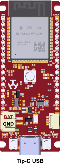
The DENEYAP Kart 1A is a versatile educational development board designed by T3 for learning and prototyping electronic circuits. It is equipped with a variety of input/output interfaces, making it an excellent choice for students, hobbyists, and professionals looking to explore electronics and programming. The board is compatible with multiple sensors and modules, enabling users to create a wide range of projects, from simple circuits to complex IoT applications.
Explore Projects Built with DENEYAP Kart 1A

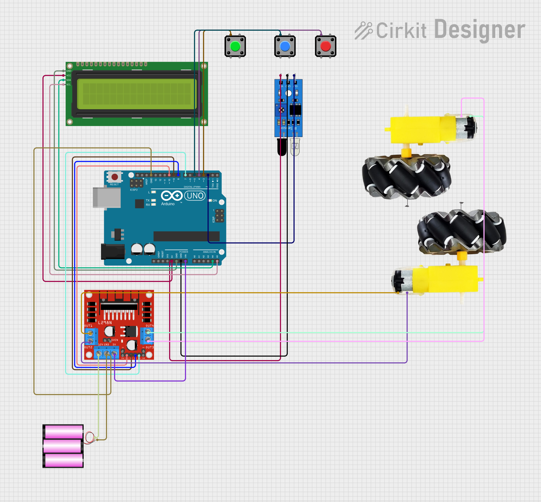
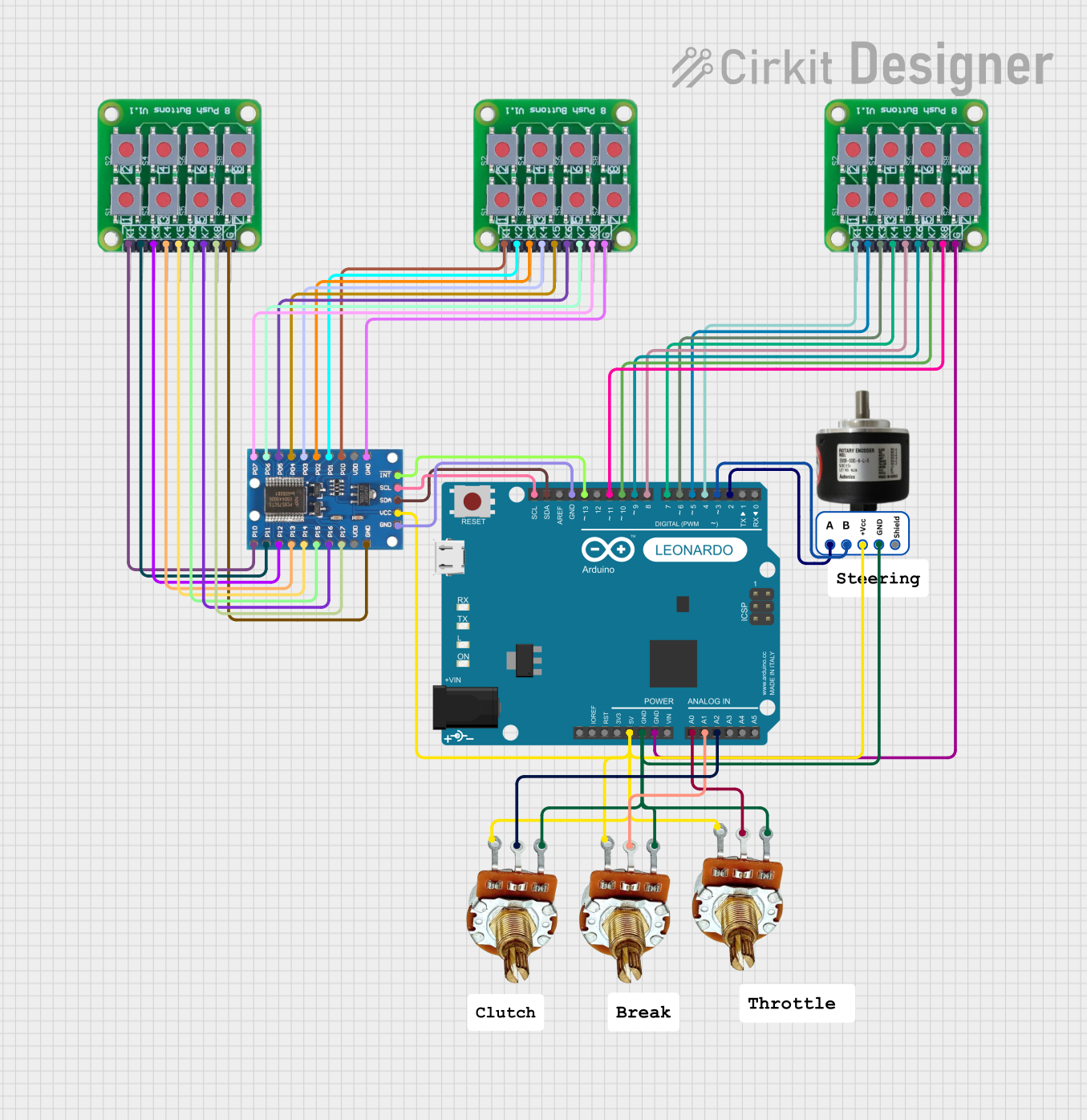
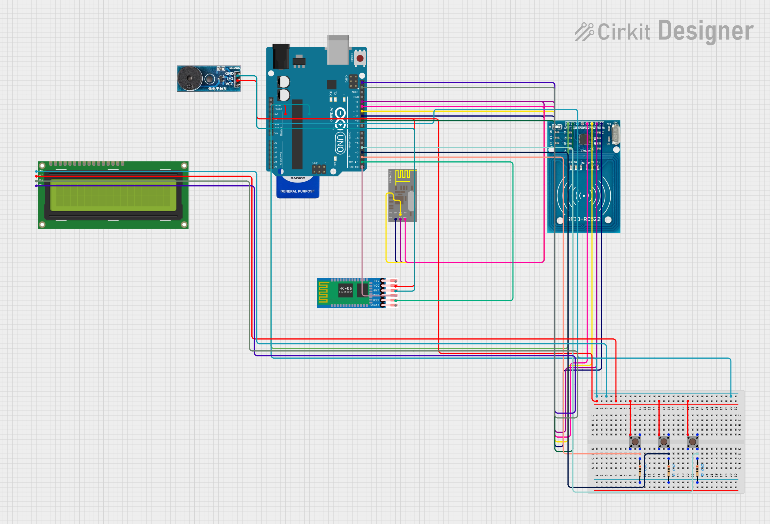
Explore Projects Built with DENEYAP Kart 1A
Common Applications and Use Cases
- Educational projects and STEM learning
- Prototyping IoT devices
- Robotics and automation systems
- Sensor-based data acquisition
- Home automation and smart devices
Technical Specifications
The following table outlines the key technical details of the DENEYAP Kart 1A:
| Specification | Details |
|---|---|
| Manufacturer | T3 |
| Part ID | V2 |
| Microcontroller | ESP32-WROOM-32 (dual-core, 32-bit processor) |
| Operating Voltage | 3.3V |
| Input Voltage Range | 5V (via USB) or 7-12V (via external power supply) |
| Digital I/O Pins | 20 (including PWM support) |
| Analog Input Pins | 6 |
| Communication Interfaces | UART, I2C, SPI, Wi-Fi, Bluetooth |
| Flash Memory | 4MB |
| Clock Speed | 240 MHz |
| Dimensions | 68mm x 53mm |
Pin Configuration and Descriptions
The DENEYAP Kart 1A features a variety of pins for connecting sensors, actuators, and other peripherals. Below is the pin configuration:
| Pin | Type | Description |
|---|---|---|
| VIN | Power Input | External power supply input (7-12V). |
| 3.3V | Power Output | Provides 3.3V for powering external components. |
| GND | Ground | Common ground for the circuit. |
| Digital Pins | Digital I/O | Configurable as input or output, supports PWM. |
| Analog Pins | Analog Input | Reads analog signals (0-3.3V). |
| TX/RX | UART | Serial communication pins. |
| SDA/SCL | I2C | Data and clock lines for I2C communication. |
| MOSI/MISO/SCK | SPI | SPI communication pins for high-speed data transfer. |
| EN | Enable | Enables or disables the microcontroller. |
| RST | Reset | Resets the board. |
Usage Instructions
How to Use the DENEYAP Kart 1A in a Circuit
Powering the Board:
- Connect the board to a computer via a USB cable for programming and power.
- Alternatively, use an external power supply (7-12V) connected to the VIN and GND pins.
Connecting Components:
- Use the digital and analog pins to connect sensors, actuators, and other peripherals.
- Ensure that the voltage and current requirements of connected components are within the board's specifications.
Programming the Board:
- The board is compatible with the Arduino IDE. Install the ESP32 board package in the Arduino IDE to program the DENEYAP Kart 1A.
- Select the appropriate board and port from the Arduino IDE settings.
Uploading Code:
- Write your code in the Arduino IDE and upload it to the board via the USB connection.
- Use the built-in serial monitor for debugging and monitoring data.
Important Considerations and Best Practices
- Avoid exceeding the maximum voltage and current ratings of the pins to prevent damage.
- Use pull-up or pull-down resistors for stable digital input signals.
- Ensure proper grounding for all connected components to avoid noise and interference.
- When using Wi-Fi or Bluetooth, ensure the board is in a location with minimal signal interference.
Example Code for Arduino UNO Compatibility
The following example demonstrates how to read an analog sensor value and control an LED using the DENEYAP Kart 1A:
// Define pin connections
const int analogPin = A0; // Analog sensor connected to A0
const int ledPin = 13;    // LED connected to digital pin 13

void setup() {
  pinMode(ledPin, OUTPUT); // Set LED pin as output
  Serial.begin(9600);      // Initialize serial communication
}

void loop() {
  int sensorValue = analogRead(analogPin); // Read analog sensor value
  Serial.print("Sensor Value: ");          // Print sensor value to serial monitor
  Serial.println(sensorValue);

  // If sensor value exceeds threshold, turn on LED
  if (sensorValue > 500) {
    digitalWrite(ledPin, HIGH); // Turn on LED
  } else {
    digitalWrite(ledPin, LOW);  // Turn off LED
  }

  delay(500); // Wait for 500ms before next reading
}
Troubleshooting and FAQs
Common Issues and Solutions
Board Not Detected by Computer:
- Ensure the USB cable is properly connected and functional.
- Install the correct USB driver for the ESP32 chip.
Code Upload Fails:
- Check that the correct board and port are selected in the Arduino IDE.
- Press and hold the "BOOT" button on the board while uploading the code.
Wi-Fi or Bluetooth Not Working:
- Verify that the correct libraries are included in your code.
- Ensure the board is in a location with minimal signal interference.
Components Not Responding:
- Double-check the wiring and connections.
- Ensure the components are compatible with the board's voltage and current ratings.
FAQs
Q: Can I use the DENEYAP Kart 1A with other development environments?
A: Yes, the board is compatible with other environments like PlatformIO and MicroPython.
Q: What is the maximum current output of the 3.3V pin?
A: The 3.3V pin can supply up to 500mA, depending on the power source.
Q: Does the board support OTA (Over-The-Air) updates?
A: Yes, the ESP32 microcontroller supports OTA updates for wireless code uploads.
Q: Can I use the board for battery-powered projects?
A: Yes, you can use a LiPo battery with a suitable voltage regulator for portable applications.