Cirkit Designer Logo
Cirkit Designer
Your all-in-one circuit design IDE
Home / 
Component Documentation

How to Use TL082: Examples, Pinouts, and Specs

Image of TL082
Cirkit Designer LogoDesign with TL082 in Cirkit Designer

Introduction

The TL082 is a low-noise JFET-input operational amplifier designed for high-speed and low-distortion applications. Manufactured under the part ID TL082, this component is widely used in audio processing, signal amplification, and instrumentation circuits. Its high input impedance and low input bias current make it ideal for precision applications, while its low noise characteristics ensure minimal signal degradation.

Explore Projects Built with TL082

Use Cirkit Designer to design, explore, and prototype these projects online. Some projects support real-time simulation. Click "Open Project" to start designing instantly!
Battery-Powered Emergency Alert System with NUCLEO-F072RB, SIM800L, and GPS NEO 6M
Image of women safety: A project utilizing TL082 in a practical application
This circuit is an emergency alert system that uses a NUCLEO-F072RB microcontroller to send SMS alerts and make calls via a SIM800L GSM module, while obtaining location data from a GPS NEO 6M module. The system is powered by a Li-ion battery and includes a TP4056 module for battery charging and protection, with a rocker switch to control power to the microcontroller.
Cirkit Designer LogoOpen Project in Cirkit Designer
Cellular-Enabled IoT Device with Real-Time Clock and Power Management
Image of LRCM PHASE 2 BASIC: A project utilizing TL082 in a practical application
This circuit features a LilyGo-SIM7000G module for cellular communication and GPS functionality, interfaced with an RTC DS3231 for real-time clock capabilities. It includes voltage sensing through two voltage sensor modules, and uses an 8-channel opto-coupler for isolating different parts of the circuit. Power management is handled by a buck converter connected to a DC power source and batteries, with a fuse for protection and a rocker switch for on/off control. Additionally, there's an LED for indication purposes.
Cirkit Designer LogoOpen Project in Cirkit Designer
Battery-Powered Health Monitoring System with Nucleo WB55RG and OLED Display
Image of Pulsefex: A project utilizing TL082 in a practical application
This circuit is a multi-sensor data acquisition system that uses a Nucleo WB55RG microcontroller to interface with a digital temperature sensor (TMP102), a pulse oximeter and heart-rate sensor (MAX30102), and a 0.96" OLED display via I2C. Additionally, it includes a Sim800l module for GSM communication, powered by a 3.7V LiPo battery.
Cirkit Designer LogoOpen Project in Cirkit Designer
NFC-Enabled Access Control System with Time Logging
Image of doorlock: A project utilizing TL082 in a practical application
This circuit is designed for access control with time tracking capabilities. It features an NFC/RFID reader for authentication, an RTC module (DS3231) for real-time clock functionality, and an OLED display for user interaction. A 12V relay controls a magnetic lock, which is activated upon successful NFC/RFID authentication, and a button switch is likely used for manual operation or input. The T8_S3 microcontroller serves as the central processing unit, interfacing with the NFC/RFID reader, RTC, OLED, and relay to manage the access control logic.
Cirkit Designer LogoOpen Project in Cirkit Designer

Explore Projects Built with TL082

Use Cirkit Designer to design, explore, and prototype these projects online. Some projects support real-time simulation. Click "Open Project" to start designing instantly!
Image of women safety: A project utilizing TL082 in a practical application
Battery-Powered Emergency Alert System with NUCLEO-F072RB, SIM800L, and GPS NEO 6M
This circuit is an emergency alert system that uses a NUCLEO-F072RB microcontroller to send SMS alerts and make calls via a SIM800L GSM module, while obtaining location data from a GPS NEO 6M module. The system is powered by a Li-ion battery and includes a TP4056 module for battery charging and protection, with a rocker switch to control power to the microcontroller.
Cirkit Designer LogoOpen Project in Cirkit Designer
Image of LRCM PHASE 2 BASIC: A project utilizing TL082 in a practical application
Cellular-Enabled IoT Device with Real-Time Clock and Power Management
This circuit features a LilyGo-SIM7000G module for cellular communication and GPS functionality, interfaced with an RTC DS3231 for real-time clock capabilities. It includes voltage sensing through two voltage sensor modules, and uses an 8-channel opto-coupler for isolating different parts of the circuit. Power management is handled by a buck converter connected to a DC power source and batteries, with a fuse for protection and a rocker switch for on/off control. Additionally, there's an LED for indication purposes.
Cirkit Designer LogoOpen Project in Cirkit Designer
Image of Pulsefex: A project utilizing TL082 in a practical application
Battery-Powered Health Monitoring System with Nucleo WB55RG and OLED Display
This circuit is a multi-sensor data acquisition system that uses a Nucleo WB55RG microcontroller to interface with a digital temperature sensor (TMP102), a pulse oximeter and heart-rate sensor (MAX30102), and a 0.96" OLED display via I2C. Additionally, it includes a Sim800l module for GSM communication, powered by a 3.7V LiPo battery.
Cirkit Designer LogoOpen Project in Cirkit Designer
Image of doorlock: A project utilizing TL082 in a practical application
NFC-Enabled Access Control System with Time Logging
This circuit is designed for access control with time tracking capabilities. It features an NFC/RFID reader for authentication, an RTC module (DS3231) for real-time clock functionality, and an OLED display for user interaction. A 12V relay controls a magnetic lock, which is activated upon successful NFC/RFID authentication, and a button switch is likely used for manual operation or input. The T8_S3 microcontroller serves as the central processing unit, interfacing with the NFC/RFID reader, RTC, OLED, and relay to manage the access control logic.
Cirkit Designer LogoOpen Project in Cirkit Designer

Common Applications

  • Audio preamplifiers and equalizers
  • Signal conditioning and processing
  • Active filters and oscillators
  • Instrumentation amplifiers
  • Analog computing and integration circuits

Technical Specifications

Key Technical Details

  • Supply Voltage (Vcc): ±3V to ±18V (dual supply) or 6V to 36V (single supply)
  • Input Offset Voltage: Typically 3mV
  • Input Bias Current: Typically 30pA
  • Slew Rate: 13V/µs (typical)
  • Gain Bandwidth Product: 3MHz (typical)
  • Input Impedance: 10⁸Ω (typical)
  • Output Voltage Swing: ±12V (with ±15V supply)
  • Quiescent Current: 1.4mA per amplifier (typical)
  • Operating Temperature Range: 0°C to 70°C
  • Package Types: DIP-8, SOIC-8

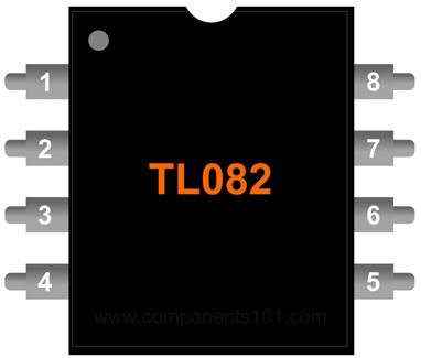
Pin Configuration and Descriptions

The TL082 is a dual operational amplifier, meaning it contains two independent op-amps in a single package. Below is the pinout for the 8-pin DIP/SOIC package:

Pin Number Pin Name Description
1 Output A Output of the first operational amplifier
2 Inverting Input A Inverting input of the first operational amplifier
3 Non-Inverting Input A Non-inverting input of the first operational amplifier
4 V- (GND) Negative power supply or ground
5 Non-Inverting Input B Non-inverting input of the second operational amplifier
6 Inverting Input B Inverting input of the second operational amplifier
7 Output B Output of the second operational amplifier
8 V+ Positive power supply

Usage Instructions

How to Use the TL082 in a Circuit

  1. Power Supply Configuration:

    • The TL082 can operate with either a single supply (e.g., 0V and +12V) or a dual supply (e.g., ±15V). Ensure the supply voltage does not exceed the absolute maximum rating of ±18V.
  2. Input Connections:

    • Connect the signal source to the non-inverting or inverting input, depending on the desired configuration (e.g., non-inverting amplifier, inverting amplifier, etc.).
    • Use appropriate resistors and capacitors to set the gain and bandwidth of the circuit.
  3. Output Load:

    • The output can drive loads with a resistance of 2kΩ or higher. For lower impedance loads, consider using a buffer stage.
  4. Bypass Capacitors:

    • Place decoupling capacitors (e.g., 0.1µF ceramic and 10µF electrolytic) close to the power supply pins to reduce noise and improve stability.
  5. Example Circuit: Non-Inverting Amplifier

    • Below is a simple non-inverting amplifier circuit using the TL082:
// Example: Non-inverting amplifier circuit
// Gain = 1 + (R2 / R1)

#include <Arduino.h>

// Define pin for analog input
const int analogInputPin = A0; // Connect signal source to A0
const int analogOutputPin = 9; // Output signal to pin 9 (PWM)

void setup() {
  pinMode(analogInputPin, INPUT); // Set input pin mode
  pinMode(analogOutputPin, OUTPUT); // Set output pin mode
}

void loop() {
  int sensorValue = analogRead(analogInputPin); // Read input signal
  int outputValue = map(sensorValue, 0, 1023, 0, 255); // Scale to PWM range
  analogWrite(analogOutputPin, outputValue); // Output amplified signal
}

Important Considerations and Best Practices

  • Input Protection: Avoid applying input voltages beyond the supply rails to prevent damage.
  • Thermal Management: Ensure adequate ventilation or heat dissipation if operating at high supply voltages.
  • Stability: Use proper feedback network design to avoid oscillations.
  • Noise Reduction: Minimize external noise by using shielded cables and proper grounding techniques.

Troubleshooting and FAQs

Common Issues and Solutions

Issue Possible Cause Solution
No output signal Incorrect power supply connection Verify V+ and V- connections
Distorted output Exceeding input or output voltage range Ensure input and output stay within range
Oscillations or instability Poor feedback network design Add compensation capacitor if needed
High noise in output Insufficient decoupling or grounding Add bypass capacitors and check grounding

FAQs

  1. Can the TL082 be used for audio applications?

    • Yes, the TL082 is well-suited for audio applications due to its low noise and high slew rate.
  2. What is the maximum gain I can achieve with the TL082?

    • The maximum gain depends on the feedback network and the bandwidth of the amplifier. For high gains, ensure the bandwidth is sufficient for your application.
  3. Can I use the TL082 with a single power supply?

    • Yes, the TL082 can operate with a single supply, but ensure the input and output signals are biased appropriately.
  4. What is the difference between the TL082 and TL072?

    • The TL082 and TL072 are similar, but the TL072 typically has slightly better noise performance and is optimized for audio applications.

By following this documentation, you can effectively integrate the TL082 into your electronic designs for reliable and high-performance operation.