
How to Use I2C HUB as Power Bar 18x: Examples, Pinouts, and Specs
 Design with I2C HUB as Power Bar 18x in Cirkit Designer
Introduction
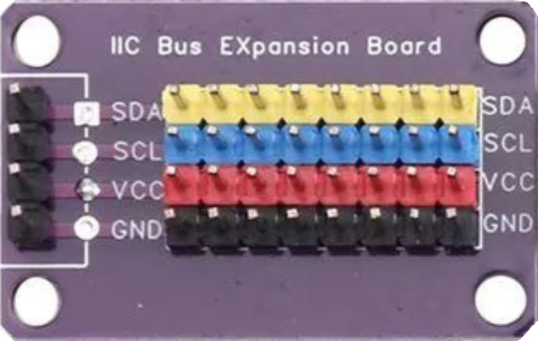
The I2C Hub as Power Distribution (PD) is a versatile electronic component designed to expand the connectivity of an I2C bus while simultaneously managing power distribution to connected devices. It allows multiple I2C slave devices to communicate with a single I2C master, ensuring efficient power delivery to each device. This component is particularly useful in applications where multiple sensors, displays, or other I2C peripherals need to be connected to a single microcontroller or processor.
Explore Projects Built with I2C HUB as Power Bar 18x
 Open Project in Cirkit Designer
 Open Project in Cirkit Designer
 Open Project in Cirkit Designer
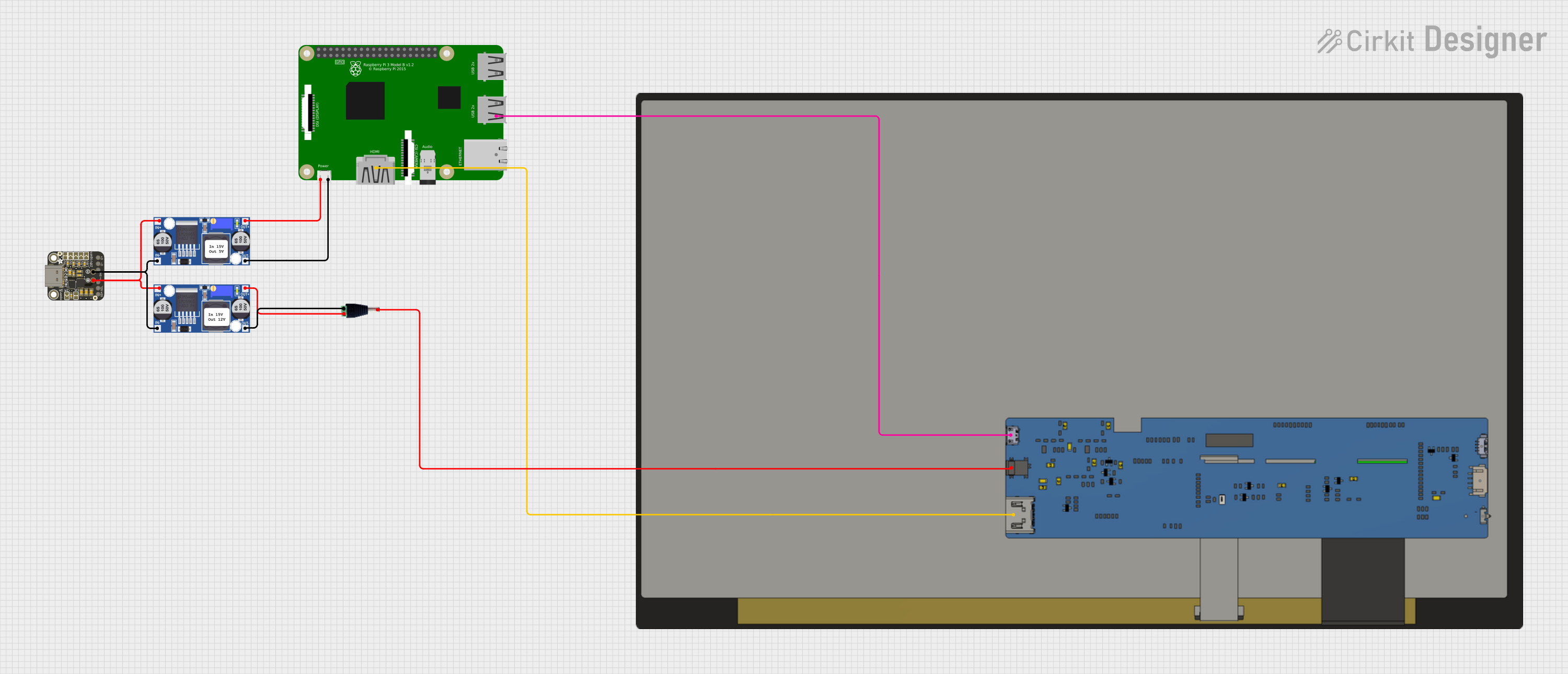 Open Project in Cirkit Designer
Explore Projects Built with I2C HUB as Power Bar 18x
Open Project in Cirkit DesignerOpen Project in Cirkit DesignerOpen Project in Cirkit DesignerOpen Project in Cirkit DesignerCommon Applications and Use Cases
- Connecting multiple I2C sensors or peripherals to a single microcontroller.
- Power management for I2C devices in embedded systems.
- Robotics and automation systems requiring multiple I2C devices.
- IoT (Internet of Things) applications with multiple sensors or actuators.
- Prototyping and development of multi-device I2C systems.
Technical Specifications
The following are the key technical details of the I2C Hub as PD:
| Parameter | Value |
|---|---|
| Operating Voltage | 3.3V to 5V |
| Maximum Current Output | 1A (shared across all connected devices) |
| I2C Bus Speed | Up to 400 kHz (Fast Mode) |
| Number of I2C Ports | 4 to 8 (depending on the specific model) |
| Power Distribution | Automatic load balancing |
| Communication Protocol | I2C (Inter-Integrated Circuit) |
| Operating Temperature | -40°C to 85°C |
Pin Configuration and Descriptions
Below is the typical pin configuration for an I2C Hub as PD:
| Pin Name | Description |
|---|---|
| VCC | Power input pin (3.3V or 5V, depending on the system requirements). |
| GND | Ground connection. |
| SDA | Serial Data Line for I2C communication. |
| SCL | Serial Clock Line for I2C communication. |
| OUT1 | I2C output port 1 for connecting a slave device. |
| OUT2 | I2C output port 2 for connecting a slave device. |
| OUT3 | I2C output port 3 for connecting a slave device. |
| OUT4 | I2C output port 4 for connecting a slave device. |
| EN | Enable pin to activate or deactivate the hub (optional, depending on the model). |
Usage Instructions
How to Use the Component in a Circuit
- Power the Hub: Connect the VCC pin to a 3.3V or 5V power source and the GND pin to the ground.
- Connect the I2C Master: Attach the SDA and SCL lines of the I2C master (e.g., a microcontroller) to the SDA and SCL pins of the hub.
- Connect I2C Slaves: Use the OUT1, OUT2, OUT3, and OUT4 ports to connect up to four I2C slave devices. Ensure that each slave device has a unique I2C address.
- Enable the Hub: If the hub has an enable pin (EN), ensure it is set to the appropriate logic level to activate the hub.
- Pull-Up Resistors: Verify that the I2C bus has appropriate pull-up resistors (typically 4.7kΩ to 10kΩ) on the SDA and SCL lines. Some hubs may have built-in pull-up resistors.
Important Considerations and Best Practices
- Power Budgeting: Ensure that the total current drawn by all connected devices does not exceed the hub's maximum current output (1A).
- I2C Address Conflicts: Avoid address conflicts by assigning unique I2C addresses to each slave device.
- Cable Length: Minimize the length of I2C cables to reduce signal degradation and noise.
- Bypass Capacitors: Place bypass capacitors (e.g., 0.1µF) near the power pins of connected devices to stabilize the power supply.
Example Code for Arduino UNO
Below is an example of how to use the I2C Hub as PD with an Arduino UNO to communicate with multiple I2C devices:
#include <Wire.h> // Include the Wire library for I2C communication

void setup() {
  Wire.begin(); // Initialize I2C communication as master
  Serial.begin(9600); // Start serial communication for debugging

  // Example: Communicate with two I2C devices
  // Device 1 has address 0x40, Device 2 has address 0x41
  Serial.println("I2C Hub as PD Example Initialized");
}

void loop() {
  // Communicate with Device 1
  Wire.beginTransmission(0x40); // Start communication with device at address 0x40
  Wire.write(0x01); // Send a command or data
  Wire.endTransmission(); // End communication

  // Communicate with Device 2
  Wire.beginTransmission(0x41); // Start communication with device at address 0x41
  Wire.write(0x02); // Send a command or data
  Wire.endTransmission(); // End communication

  delay(1000); // Wait for 1 second before repeating
}
Troubleshooting and FAQs
Common Issues and Solutions
No Communication with Slave Devices
- Cause: Incorrect wiring or loose connections.
- Solution: Double-check all connections, ensuring SDA and SCL lines are properly connected.
I2C Address Conflicts
- Cause: Two or more devices have the same I2C address.
- Solution: Reconfigure the I2C addresses of the conflicting devices (if possible).
Power Overload
- Cause: Total current draw exceeds the hub's maximum output.
- Solution: Reduce the number of connected devices or use devices with lower power consumption.
Signal Degradation
- Cause: Long I2C cables or high capacitance on the bus.
- Solution: Shorten the cables and ensure proper pull-up resistor values.
FAQs
Q1: Can I connect more than four devices to the hub?
A1: Some models of the I2C Hub as PD support more than four ports. If additional devices are needed, consider using a hub with more ports or cascading multiple hubs.
Q2: Does the hub support 5V and 3.3V devices simultaneously?
A2: Most hubs operate at a single voltage level. Use level shifters if you need to connect devices with different voltage levels.
Q3: Do I need external pull-up resistors?
A3: Some hubs have built-in pull-up resistors. If not, you will need to add external pull-up resistors to the SDA and SCL lines.
Q4: What happens if the hub overheats?
A4: Many hubs include thermal protection. If overheating occurs, reduce the load or improve ventilation.