How to Use USB Hub: Examples, Pinouts, and Specs
Introduction
A USB hub is a device that expands a single USB port into multiple ports, enabling the connection of multiple USB devices to a computer or other host device simultaneously. It acts as a central point for managing USB peripherals such as keyboards, mice, flash drives, printers, and external hard drives. USB hubs are available in powered and unpowered variants, with powered hubs providing additional current to support high-power devices.
Explore Projects Built with USB Hub


Explore Projects Built with USB Hub
Common Applications and Use Cases
- Expanding the number of USB ports on laptops or desktops.
- Connecting multiple peripherals like keyboards, mice, and printers.
- Charging multiple USB devices simultaneously (in powered hubs).
- Managing USB devices in embedded systems or IoT projects.
- Simplifying cable management in workstations.
Technical Specifications
Below are the general technical specifications for a typical USB hub. Specifications may vary depending on the model and manufacturer.
Key Technical Details
- USB Standards Supported: USB 2.0, USB 3.0, USB 3.1, or USB-C (varies by model)
- Number of Ports: Typically 4 to 10 ports
- Power Supply:
- Bus-powered (draws power from the host device)
- Self-powered (uses an external power adapter)
- Data Transfer Rate:
- USB 2.0: Up to 480 Mbps
- USB 3.0: Up to 5 Gbps
- USB 3.1: Up to 10 Gbps
- Input Voltage: 5V DC (for powered hubs)
- Current Output per Port:
- Bus-powered: Typically 100mA to 500mA
- Powered: Up to 900mA or more per port
- Operating Temperature: 0°C to 40°C
- Compatibility: Windows, macOS, Linux, and other USB-compliant systems
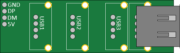
Pin Configuration and Descriptions
USB hubs typically do not have exposed pins for user interaction, as they use standard USB connectors. However, the following table describes the pinout of a USB Type-A connector, which is commonly used in USB hubs.
| Pin Number | Name | Description |
|---|---|---|
| 1 | VBUS | +5V DC power supply |
| 2 | D- | Data line (negative) |
| 3 | D+ | Data line (positive) |
| 4 | GND | Ground |
For USB-C hubs, the pinout is more complex and supports additional features like power delivery and alternate modes.
Usage Instructions
How to Use the USB Hub in a Circuit
- Connect the Hub to the Host Device: Plug the USB hub's upstream port into the USB port of your computer or host device.
- Connect USB Devices: Plug your USB peripherals (e.g., keyboard, mouse, flash drive) into the downstream ports of the hub.
- Power the Hub (if required): For powered hubs, connect the external power adapter to the hub and plug it into a power outlet.
- Verify Connections: Ensure all devices are recognized by the host system. Check the device manager (Windows) or system information (macOS) for connected devices.
Important Considerations and Best Practices
- Choose the Right Hub: Select a hub that supports the USB standard required by your devices (e.g., USB 3.0 for high-speed data transfer).
- Power Requirements: Use a powered hub for devices that require more current, such as external hard drives or charging multiple devices.
- Cable Length: Avoid using excessively long cables to minimize signal degradation.
- Overloading: Do not connect more devices than the hub can support, as this may cause performance issues or damage the hub.
- Firmware Updates: Check for firmware updates from the manufacturer to ensure compatibility with the latest devices.
Example: Connecting a USB Hub to an Arduino UNO
While USB hubs are not directly programmable, they can be used to connect multiple USB devices to an Arduino UNO via a USB host shield. Below is an example of Arduino code to interface with a USB keyboard connected through a USB hub.
#include <KeyboardController.h>
#include <Usb.h>

// Initialize USB host object
USBHost usb;

// Initialize keyboard controller object
KeyboardController keyboard(&usb);

void setup() {
  Serial.begin(9600);
  while (!Serial) {
    // Wait for the serial connection to initialize
  }
  Serial.println("USB Hub Example: Keyboard Input");
}

void loop() {
  usb.Task(); // Poll the USB host for events

  // Check if a key is pressed
  if (keyboard.available()) {
    char key = keyboard.getKey();
    Serial.print("Key Pressed: ");
    Serial.println(key);
  }
}
Note: This example requires a USB host shield and the appropriate libraries installed in the Arduino IDE.
Troubleshooting and FAQs
Common Issues and Solutions
Devices Not Recognized:
- Ensure the hub is properly connected to the host device.
- Check if the hub requires external power and ensure the power adapter is connected.
- Verify that the USB drivers on the host device are up to date.
Slow Data Transfer Speeds:
- Confirm that the hub and connected devices support the same USB standard (e.g., USB 3.0).
- Avoid using long or low-quality USB cables.
Overheating:
- Do not overload the hub with too many high-power devices.
- Use a powered hub to distribute power more effectively.
Intermittent Connections:
- Check for loose or damaged cables.
- Ensure the hub is placed on a stable surface to avoid movement.
FAQs
Can I use a USB hub to charge devices? Yes, powered USB hubs can charge devices. However, the charging speed depends on the hub's current output per port.
Can I daisy-chain multiple USB hubs? Yes, but USB standards limit the number of hubs in a chain to 5. Performance may degrade with each additional hub.
Do USB hubs work with all operating systems? Most USB hubs are plug-and-play and work with Windows, macOS, Linux, and other USB-compliant systems without additional drivers.
What is the difference between a powered and unpowered USB hub? A powered hub uses an external power adapter to supply additional current, while an unpowered hub draws power from the host device. Powered hubs are better for high-power devices.