How to Use Serial Enabled 16x2 LCD - Black on Green 5V: Examples, Pinouts, and Specs
Introduction
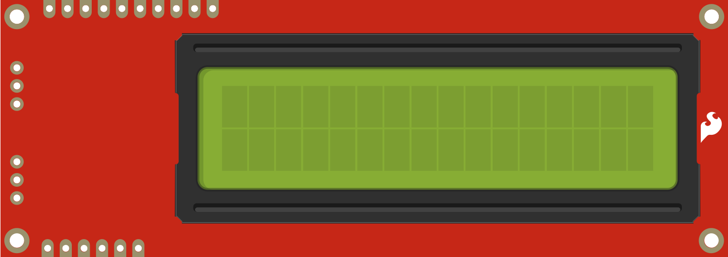
The Serial Enabled 16x2 LCD - Black on Green 5V is a versatile and user-friendly display module that allows users to add a readable interface to their electronic projects. This component features a 16-character by 2-line liquid crystal display capable of displaying letters, numbers, and special characters. With its serial communication interface, it simplifies the process of integrating a display into projects, requiring fewer pins than parallel LCDs and making it ideal for microcontroller-based applications, such as Arduino projects.
Explore Projects Built with Serial Enabled 16x2 LCD - Black on Green 5V
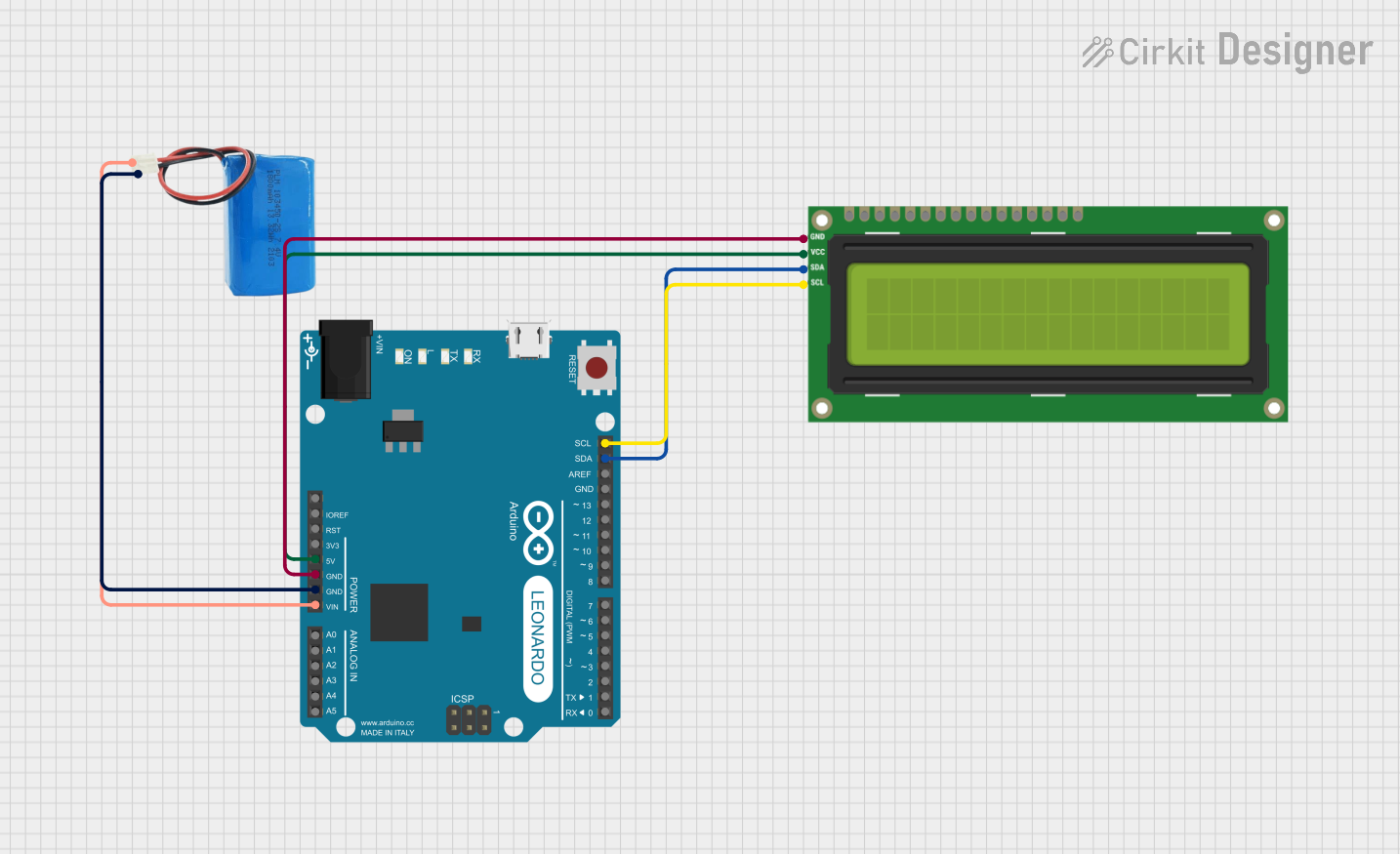

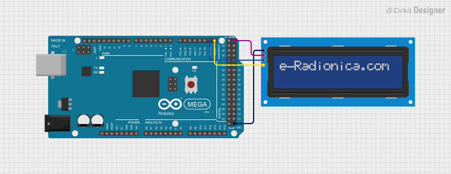
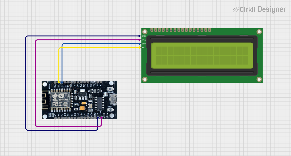
Explore Projects Built with Serial Enabled 16x2 LCD - Black on Green 5V
Common Applications and Use Cases
- User interfaces for electronic devices
- Real-time data output displays
- Menu systems for settings and options
- Debugging tool for displaying system statuses
Technical Specifications
Key Technical Details
- Operating Voltage: 5V
- Display Type: 16 characters x 2 lines
- Backlight: Green LED
- Character Color: Black
- Communication: Serial (TTL)
- Baud Rate: Configurable (default 9600 bps)
Pin Configuration and Descriptions
| Pin Number | Name | Description |
|---|---|---|
| 1 | VSS | Ground |
| 2 | VDD | +5V Supply |
| 3 | VE | Contrast Adjust |
| 4 | RS | Register Select for Instruction/Data |
| 5 | R/W | Read/Write Signal (GND for write) |
| 6 | E | Enable Signal |
| 7-14 | D0-D7 | Data Bus Pins (Not used in serial mode) |
| 15 | A | Anode for Backlight (+5V) |
| 16 | K | Cathode for Backlight (GND) |
| 17 | RX | Serial Receive Pin |
| 18 | TX | Serial Transmit Pin (Not used; leave unconnected) |
Usage Instructions
How to Use the Component in a Circuit
- Connect the VSS pin to the ground of your power supply.
- Connect the VDD pin to a +5V supply.
- Adjust the VE pin for desired contrast, or connect it to a potentiometer for adjustable contrast.
- Connect the RX pin to the TX pin of your microcontroller.
- Optionally, connect the A and K pins to +5V and ground, respectively, to power the backlight.
Important Considerations and Best Practices
- Always ensure that the power supply does not exceed 5V as it may damage the LCD.
- Use a current-limiting resistor if connecting the backlight directly to 5V.
- For longer cable runs, consider using shielded cables to reduce noise on the serial line.
- Avoid placing the LCD in direct sunlight or high-temperature environments to prevent damage.
Example Code for Arduino UNO
#include <SoftwareSerial.h>

SoftwareSerial mySerial(10, 11); // RX, TX

void setup() {
  // Set the baud rate to match the LCD's default baud rate
  mySerial.begin(9600);

  // Clear the screen
  mySerial.write(0x7C);
  mySerial.write(0x2D);
}

void loop() {
  // Set the cursor to the beginning of the first line
  mySerial.write(0xFE);
  mySerial.write(0x80);

  // Print a message on the first line
  mySerial.print("Hello, World!");

  // Set the cursor to the beginning of the second line
  mySerial.write(0xFE);
  mySerial.write(0xC0);

  // Print a message on the second line
  mySerial.print("Serial LCD Demo");

  // Wait for 3 seconds
  delay(3000);

  // Clear the screen before looping
  mySerial.write(0x7C);
  mySerial.write(0x2D);
}
Troubleshooting and FAQs
Common Issues Users Might Face
- Display not powering on: Check the power connections and ensure the supply is 5V.
- Characters not visible or dim: Adjust the contrast using the VE pin or check the backlight connections.
- Garbled or incorrect characters: Ensure the baud rate of the microcontroller matches the LCD's baud rate.
Solutions and Tips for Troubleshooting
- If the display is not responding, try resetting the power to the LCD.
- Ensure that the serial connections are secure and there is no loose wiring.
- If using long wires, keep them away from high-power lines to avoid electromagnetic interference.
FAQs
Q: Can I use this LCD with a 3.3V system? A: No, this LCD is designed for 5V operation. Using it with 3.3V may result in dim or unreadable characters.
Q: How do I change the baud rate of the LCD? A: The baud rate can be changed using a specific command sequence, which is detailed in the LCD's datasheet.
Q: Can I use this LCD without an Arduino? A: Yes, any microcontroller with a UART interface can be used to communicate with the LCD.
Q: Is it possible to create custom characters? A: Yes, the LCD supports custom characters. You can define them using the appropriate command sequence.