How to Use pMOS Transistor (MOSFET): Examples, Pinouts, and Specs

Introduction
A pMOS transistor, or p-channel Metal-Oxide-Semiconductor Field-Effect Transistor (MOSFET), is a widely used electronic component that functions as a switch or amplifier in electronic circuits. Unlike its counterpart, the nMOS transistor, the pMOS uses a p-type semiconductor as the channel through which current flows. It is typically used in applications where load switching, power management, and signal amplification are required. Common applications include power supply circuits, motor control, and as a part of integrated circuits in various electronic devices.
Explore Projects Built with pMOS Transistor (MOSFET)


Explore Projects Built with pMOS Transistor (MOSFET)
Technical Specifications
Key Technical Details
- Threshold Voltage (Vth): The minimum gate-to-source voltage required to turn the transistor on.
- Drain-Source Voltage (Vds): The maximum voltage that can be applied across the drain-source terminals.
- Gate-Source Voltage (Vgs): The voltage applied between the gate and source terminals to control the transistor.
- Continuous Drain Current (Id): The maximum current that can flow through the drain terminal when the transistor is on.
- Power Dissipation (Pd): The maximum power the transistor can dissipate without damage.
Pin Configuration and Descriptions
| Pin Number | Name | Description |
|---|---|---|
| 1 | Gate (G) | Controls the operation of the transistor; voltage applied here regulates current flow. |
| 2 | Drain (D) | The terminal through which the controlled current leaves the transistor. |
| 3 | Source (S) | The terminal through which the controlled current enters the transistor. |
Usage Instructions
How to Use the pMOS Transistor in a Circuit
- Identify the Pins: Refer to the pin configuration table to correctly identify the gate, drain, and source pins.
- Gate Voltage: Apply a negative voltage (relative to the source) to the gate to turn the pMOS on. The voltage should be greater than the threshold voltage (Vth).
- Load Connection: Connect the load to the drain terminal, ensuring that the voltage and current ratings do not exceed the transistor's specifications.
- Source Terminal: Connect the source terminal to the higher potential of your power supply.
- Biasing: Properly bias the transistor by ensuring that the gate-source voltage is within the specified range for your application.
Important Considerations and Best Practices
- Heat Management: Use a heatsink if the power dissipation is expected to be high.
- Gate Protection: A resistor in series with the gate can protect against voltage spikes.
- Voltage Ratings: Always stay within the recommended voltage and current ratings to prevent damage.
- Switching Speed: Be aware of the switching speed and gate charge characteristics, which can affect performance in high-frequency applications.
Troubleshooting and FAQs
Common Issues
- Transistor Not Switching: Ensure that the gate voltage is sufficient to surpass the threshold voltage.
- Overheating: Check for excessive power dissipation and ensure adequate cooling.
- Unexpected Behavior: Verify that the source is connected to the higher potential, as reversing the drain and source can cause malfunction.
Solutions and Tips for Troubleshooting
- Gate Voltage: If the transistor is not turning on, increase the gate voltage incrementally while monitoring the drain current.
- Check Connections: Revisit all connections to ensure they are secure and correct.
- Measure Voltages: Use a multimeter to measure the voltages at the gate, source, and drain to ensure they match the expected values.
FAQs
Q: Can I use a pMOS transistor to switch a high current load? A: Yes, but ensure the transistor's current rating can handle the load and that proper heat dissipation methods are in place.
Q: How do I choose a resistor for the gate? A: The gate resistor value is chosen based on the desired switching speed and gate charge characteristics. A common value is between 10Ω to 1kΩ.
Q: What happens if I reverse the drain and source connections? A: The pMOS may not operate correctly, as the built-in diode between the source and drain will become forward-biased, potentially causing a short circuit.
Example Code for Arduino UNO
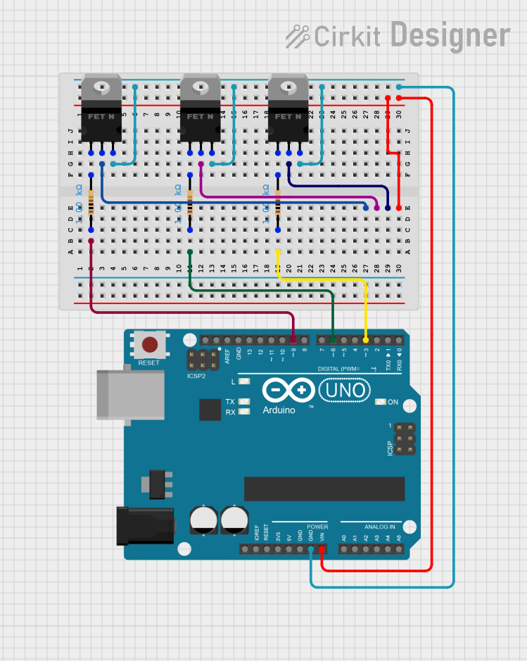
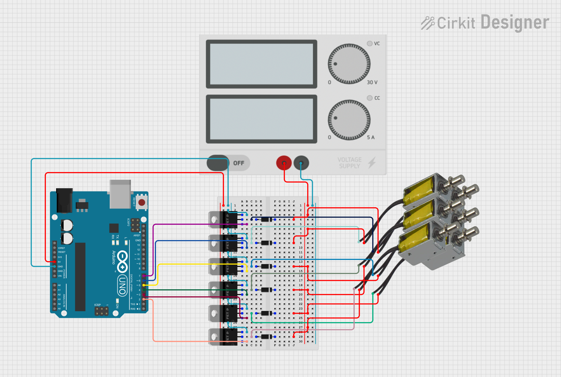
Below is an example of how to use a pMOS transistor with an Arduino UNO to switch a high-power LED on and off.
// Define the pin connected to the gate of the pMOS
const int gatePin = 3;

void setup() {
  // Set the gate pin as an output
  pinMode(gatePin, OUTPUT);
}

void loop() {
  // Turn the pMOS on (LED off)
  digitalWrite(gatePin, HIGH); // Apply HIGH to turn pMOS off due to negative logic
  delay(1000); // Wait for 1 second

  // Turn the pMOS off (LED on)
  digitalWrite(gatePin, LOW); // Apply LOW to turn pMOS on
  delay(1000); // Wait for 1 second
}
Note: In this example, the LED is connected to the drain of the pMOS, and the source is connected to the positive supply voltage. The Arduino pin drives the gate with a LOW signal to turn the pMOS on (allowing current to flow through the LED) and a HIGH signal to turn it off. Remember to include a current-limiting resistor in series with the LED to prevent damage.