Cirkit Designer Logo
Cirkit Designer
Your all-in-one circuit design IDE
Home / 
Component Documentation

How to Use Panel LED 16 x 16: Examples, Pinouts, and Specs

Image of Panel LED 16 x 16
Cirkit Designer LogoDesign with Panel LED 16 x 16 in Cirkit Designer

Introduction

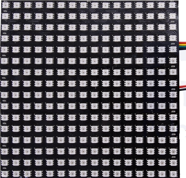
The Panel LED 16 x 16 is a matrix of 256 individual LEDs arranged in a 16x16 grid. This component is widely used for displaying images, scrolling text, or animations in various electronic projects. It is a versatile and visually appealing display solution for hobbyists, students, and professionals alike. The panel is often used in applications such as digital signage, decorative lighting, gaming displays, and educational projects.

Explore Projects Built with Panel LED 16 x 16

Use Cirkit Designer to design, explore, and prototype these projects online. Some projects support real-time simulation. Click "Open Project" to start designing instantly!
Arduino UNO-Based Interactive LED Game with 8x8 Matrix and TM1637 Display
Image of Gra_na_refleks: A project utilizing Panel LED 16 x 16 in a practical application
This circuit is a game system controlled by an Arduino UNO, featuring an 8x8 LED matrix, a 4x4 keypad, and a TM1637 4-digit display. The user interacts with the game via the keypad, and the game state is displayed on the LED matrix and the TM1637 display, with power supplied by a 9V battery.
Cirkit Designer LogoOpen Project in Cirkit Designer
Arduino UNO Controlled Interactive Display with Joystick and Buzzer Feedback
Image of joystick: A project utilizing Panel LED 16 x 16 in a practical application
This circuit features an Arduino UNO microcontroller connected to an 8x8 LED matrix, an LCD display with I2C interface, a KY-023 Dual Axis Joystick Module, and a Piezo Buzzer. The Arduino controls the LED matrix via digital pins and provides an interface for the joystick's analog inputs and button press. The LCD display is used for output, and the buzzer is driven by a digital pin for audio feedback.
Cirkit Designer LogoOpen Project in Cirkit Designer
Battery-Powered LED Control System with Push Switches and Boost Converter
Image of Power Setup Updated 10/12: A project utilizing Panel LED 16 x 16 in a practical application
This circuit consists of multiple LEDs, push switches, and power jacks, designed to control the illumination of the LEDs. Each LED is connected to a power jack through a push switch, allowing individual control of each LED. Additionally, the circuit includes a 7-inch WaveShare display, a boost converter, and fans, all powered through a terminal block.
Cirkit Designer LogoOpen Project in Cirkit Designer
Arduino UNO Controlled LED Matrix Display with Interactive Pushbuttons
Image of Cykel: A project utilizing Panel LED 16 x 16 in a practical application
This circuit features an Arduino UNO microcontroller connected to multiple 8x8 LED matrix displays and pushbuttons. The pushbuttons are interfaced with digital pins D2, D3, and D4 on the Arduino for input, while the LED matrices are connected to digital pins D5 through D10 for control signals. Additionally, there is a single red LED with a series resistor connected to pin D12, likely used as an indicator light.
Cirkit Designer LogoOpen Project in Cirkit Designer

Explore Projects Built with Panel LED 16 x 16

Use Cirkit Designer to design, explore, and prototype these projects online. Some projects support real-time simulation. Click "Open Project" to start designing instantly!
Image of Gra_na_refleks: A project utilizing Panel LED 16 x 16 in a practical application
Arduino UNO-Based Interactive LED Game with 8x8 Matrix and TM1637 Display
This circuit is a game system controlled by an Arduino UNO, featuring an 8x8 LED matrix, a 4x4 keypad, and a TM1637 4-digit display. The user interacts with the game via the keypad, and the game state is displayed on the LED matrix and the TM1637 display, with power supplied by a 9V battery.
Cirkit Designer LogoOpen Project in Cirkit Designer
Image of joystick: A project utilizing Panel LED 16 x 16 in a practical application
Arduino UNO Controlled Interactive Display with Joystick and Buzzer Feedback
This circuit features an Arduino UNO microcontroller connected to an 8x8 LED matrix, an LCD display with I2C interface, a KY-023 Dual Axis Joystick Module, and a Piezo Buzzer. The Arduino controls the LED matrix via digital pins and provides an interface for the joystick's analog inputs and button press. The LCD display is used for output, and the buzzer is driven by a digital pin for audio feedback.
Cirkit Designer LogoOpen Project in Cirkit Designer
Image of Power Setup Updated 10/12: A project utilizing Panel LED 16 x 16 in a practical application
Battery-Powered LED Control System with Push Switches and Boost Converter
This circuit consists of multiple LEDs, push switches, and power jacks, designed to control the illumination of the LEDs. Each LED is connected to a power jack through a push switch, allowing individual control of each LED. Additionally, the circuit includes a 7-inch WaveShare display, a boost converter, and fans, all powered through a terminal block.
Cirkit Designer LogoOpen Project in Cirkit Designer
Image of Cykel: A project utilizing Panel LED 16 x 16 in a practical application
Arduino UNO Controlled LED Matrix Display with Interactive Pushbuttons
This circuit features an Arduino UNO microcontroller connected to multiple 8x8 LED matrix displays and pushbuttons. The pushbuttons are interfaced with digital pins D2, D3, and D4 on the Arduino for input, while the LED matrices are connected to digital pins D5 through D10 for control signals. Additionally, there is a single red LED with a series resistor connected to pin D12, likely used as an indicator light.
Cirkit Designer LogoOpen Project in Cirkit Designer

Technical Specifications

  • LED Configuration: 16 rows x 16 columns (256 LEDs total)
  • Operating Voltage: Typically 5V DC
  • Current Consumption: Varies based on brightness and number of active LEDs (average: ~2A at full brightness)
  • Control Interface: Serial (SPI or I2C, depending on the driver IC)
  • Driver IC: Commonly uses MAX7219, HT16K33, or similar
  • Dimensions: ~160mm x 160mm (varies by manufacturer)
  • Pixel Pitch: ~10mm (varies by model)
  • Color Options: Single-color (e.g., red, green, blue) or RGB (full color)

Pin Configuration and Descriptions

The pin configuration may vary depending on the specific driver IC used. Below is a general example for a panel using the MAX7219 driver IC:

Pin Name Description
VCC Power supply input (typically 5V DC)
GND Ground connection
DIN Serial data input
CS Chip select (latch)
CLK Clock signal input

For RGB LED panels, additional pins for red, green, and blue channels may be present, along with a more complex control interface.

Usage Instructions

How to Use the Panel LED 16 x 16 in a Circuit

  1. Power Supply: Connect the VCC and GND pins to a stable 5V DC power source. Ensure the power supply can handle the current requirements of the panel.
  2. Data Connection: Use the DIN, CS, and CLK pins to interface with a microcontroller (e.g., Arduino UNO). These pins are used to send data and control signals to the panel.
  3. Driver Library: Install a suitable library for the driver IC (e.g., LedControl for MAX7219 or Adafruit_GFX for RGB panels).
  4. Programming: Write code to send data to the panel, controlling which LEDs are lit and their brightness.

Important Considerations and Best Practices

  • Power Requirements: Ensure your power supply can provide sufficient current, especially for RGB panels at full brightness.
  • Heat Management: Prolonged use at high brightness may generate heat. Consider adding ventilation or heat sinks if necessary.
  • Data Timing: Follow the timing requirements specified in the driver IC datasheet to ensure proper communication.
  • Avoid Overdriving LEDs: Exceeding the recommended voltage or current can damage the LEDs.

Example Code for Arduino UNO

Below is an example of how to control a 16x16 LED panel with the MAX7219 driver using the LedControl library:

#include <LedControl.h>

// Initialize the LedControl library
// Parameters: DIN pin, CLK pin, CS pin, number of devices
LedControl lc = LedControl(12, 11, 10, 1);

void setup() {
  // Wake up the MAX7219 from power-saving mode
  lc.shutdown(0, false);
  // Set brightness (0-15)
  lc.setIntensity(0, 8);
  // Clear the display
  lc.clearDisplay(0);
}

void loop() {
  // Example: Light up a single LED at row 0, column 0
  lc.setLed(0, 0, 0, true); // Device 0, row 0, column 0, LED ON
  delay(500);

  // Turn off the LED
  lc.setLed(0, 0, 0, false);
  delay(500);

  // Example: Light up all LEDs in a diagonal pattern
  for (int i = 0; i < 8; i++) {
    lc.setLed(0, i, i, true); // Light up diagonal LEDs
    delay(100);
  }
}

Troubleshooting and FAQs

Common Issues

  1. No LEDs Lighting Up:

    • Check the power supply connections and ensure the voltage is correct.
    • Verify that the DIN, CS, and CLK pins are properly connected to the microcontroller.
    • Ensure the driver IC is not in shutdown mode (use the appropriate library function to wake it up).
  2. Flickering LEDs:

    • Check for loose connections or poor solder joints.
    • Ensure the power supply can handle the current requirements of the panel.
  3. Incorrect LED Patterns:

    • Verify that the data being sent matches the panel's configuration.
    • Check the timing and protocol used in the code.

FAQs

Q: Can I daisy-chain multiple panels?
A: Yes, many panels with driver ICs like MAX7219 support daisy-chaining. Connect the DOUT pin of one panel to the DIN pin of the next, and adjust the code to address multiple devices.

Q: How do I control RGB panels?
A: RGB panels require more complex control, often using libraries like Adafruit_NeoMatrix or FastLED. Refer to the specific panel's datasheet for details.

Q: Can I power the panel directly from the Arduino?
A: No, the Arduino cannot supply enough current for the panel. Use an external 5V power supply.