
How to Use esp32 c3 super mini: Examples, Pinouts, and Specs
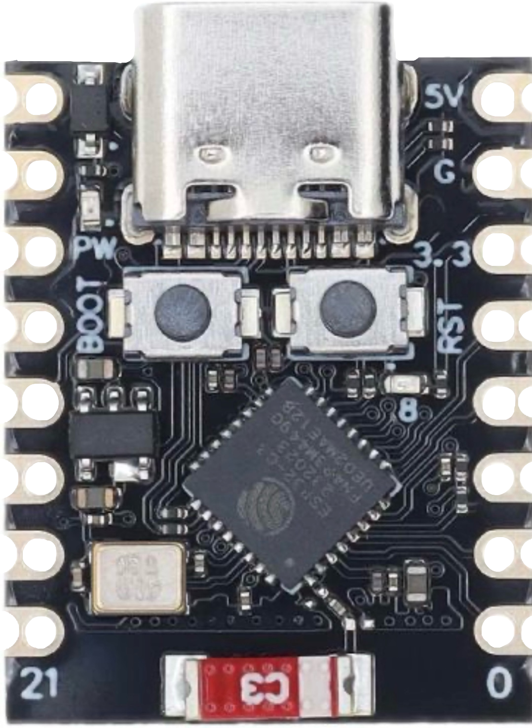
 Design with esp32 c3 super mini in Cirkit Designer
Introduction
The ESP32 C3 Super Mini, manufactured by Espressif, is a compact and low-power microcontroller designed for IoT applications. It features integrated Wi-Fi and Bluetooth Low Energy (BLE) capabilities, making it ideal for wireless communication tasks. Built on a RISC-V architecture, the ESP32 C3 Super Mini offers efficient performance for a wide range of applications, including smart home devices, wearables, and industrial IoT systems.
Explore Projects Built with esp32 c3 super mini
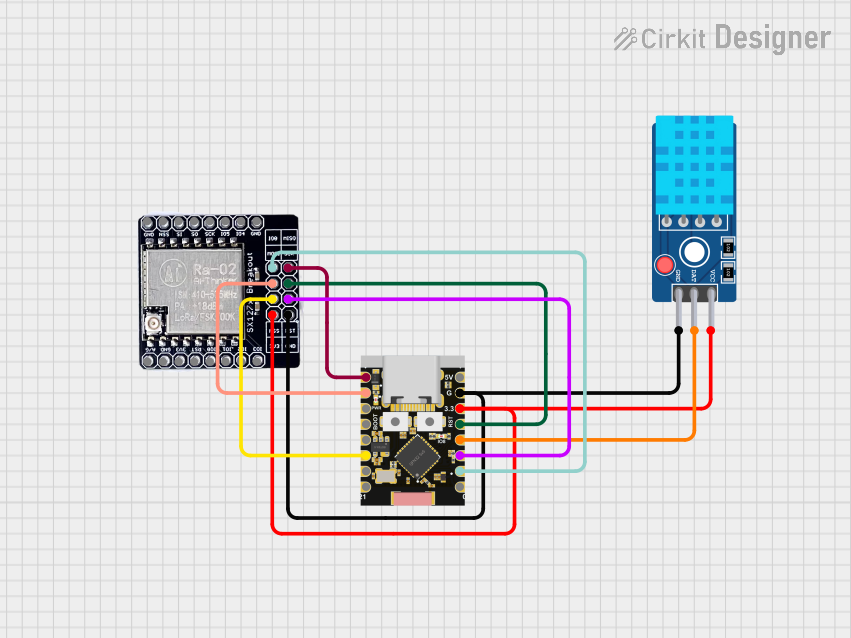 Open Project in Cirkit Designer
 Open Project in Cirkit Designer
 Open Project in Cirkit Designer
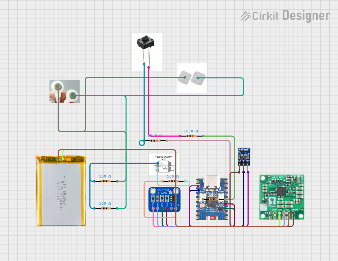 Open Project in Cirkit Designer
Explore Projects Built with esp32 c3 super mini
Open Project in Cirkit DesignerOpen Project in Cirkit DesignerOpen Project in Cirkit DesignerOpen Project in Cirkit DesignerCommon Applications and Use Cases
- Smart home automation (e.g., connected lights, thermostats)
- Wearable devices with wireless connectivity
- Industrial IoT systems for monitoring and control
- Wireless sensor networks
- Prototyping and development of IoT projects
Technical Specifications
The ESP32 C3 Super Mini is packed with features that make it versatile and powerful for IoT applications. Below are its key technical specifications:
| Specification | Details |
|---|---|
| Microcontroller Core | RISC-V single-core processor, up to 160 MHz |
| Flash Memory | 4 MB (varies by model) |
| RAM | 400 KB SRAM |
| Wi-Fi | IEEE 802.11 b/g/n (2.4 GHz) |
| Bluetooth | Bluetooth 5.0 Low Energy (BLE) |
| GPIO Pins | 22 GPIO pins (multiplexed for various functions) |
| Operating Voltage | 3.3V |
| Power Supply | 5V via USB or 3.3V via external power |
| Communication Interfaces | UART, SPI, I2C, I2S, PWM, ADC |
| ADC Resolution | 12-bit |
| Operating Temperature | -40°C to +85°C |
| Dimensions | 18 mm x 25.5 mm |
Pin Configuration and Descriptions
The ESP32 C3 Super Mini has a compact pinout. Below is the pin configuration:
| Pin | Name | Description |
|---|---|---|
| 1 | 3V3 | 3.3V power output |
| 2 | GND | Ground |
| 3 | GPIO0 | General-purpose I/O, boot mode selection |
| 4 | GPIO1 | General-purpose I/O, UART TX |
| 5 | GPIO2 | General-purpose I/O, UART RX |
| 6 | GPIO3 | General-purpose I/O, supports PWM |
| 7 | GPIO4 | General-purpose I/O, ADC input |
| 8 | GPIO5 | General-purpose I/O, SPI clock |
| 9 | EN | Enable pin, used to reset the module |
| 10 | RXD | UART receive pin |
| 11 | TXD | UART transmit pin |
| 12 | USB D+ | USB data positive |
| 13 | USB D- | USB data negative |
Usage Instructions
How to Use the ESP32 C3 Super Mini in a Circuit
Powering the Module:
- Connect the 5V pin to a 5V power source or use the USB interface for power.
- Ensure the GND pin is connected to the ground of your circuit.
Programming the Module:
- Use the USB interface to connect the ESP32 C3 Super Mini to your computer.
- Install the necessary drivers and use the Arduino IDE or Espressif's ESP-IDF for programming.
Connecting Peripherals:
- Use the GPIO pins for connecting sensors, actuators, or other peripherals.
- Ensure the voltage levels of connected devices are compatible with the 3.3V logic of the ESP32 C3.
Wireless Communication:
- Configure Wi-Fi and Bluetooth settings in your code to enable wireless communication.
- Use the provided libraries in the Arduino IDE or ESP-IDF for seamless integration.
Important Considerations and Best Practices
- Voltage Levels: Ensure all connected peripherals operate at 3.3V logic levels to avoid damaging the module.
- Boot Mode: To enter bootloader mode, hold the GPIO0 pin low while resetting the module.
- Antenna Placement: Avoid placing metal objects near the onboard antenna to ensure optimal wireless performance.
- Power Supply: Use a stable power source to prevent unexpected resets or performance issues.
Example Code for Arduino UNO Integration
Below is an example of how to use the ESP32 C3 Super Mini with the Arduino IDE to connect to a Wi-Fi network:
#include <WiFi.h> // Include the Wi-Fi library for ESP32

// Replace with your network credentials
const char* ssid = "Your_SSID";
const char* password = "Your_PASSWORD";

void setup() {
  Serial.begin(115200); // Initialize serial communication at 115200 baud
  delay(1000); // Wait for a second to stabilize the serial monitor

  Serial.println("Connecting to Wi-Fi...");
  WiFi.begin(ssid, password); // Start connecting to the Wi-Fi network

  while (WiFi.status() != WL_CONNECTED) {
    delay(500); // Wait for 500ms before checking the connection status again
    Serial.print(".");
  }

  Serial.println("\nWi-Fi connected!");
  Serial.print("IP Address: ");
  Serial.println(WiFi.localIP()); // Print the assigned IP address
}

void loop() {
  // Add your main code here
}
Troubleshooting and FAQs
Common Issues and Solutions
Module Not Detected by Computer:
- Ensure the USB cable is functional and supports data transfer.
- Install the correct USB-to-serial drivers for the ESP32 C3 Super Mini.
Wi-Fi Connection Fails:
- Double-check the SSID and password in your code.
- Ensure the Wi-Fi network is within range and operational.
Module Keeps Resetting:
- Verify that the power supply is stable and provides sufficient current.
- Check for short circuits or incorrect connections in your circuit.
Bluetooth Not Working:
- Ensure Bluetooth is enabled in your code and the device is discoverable.
- Check for interference from other wireless devices.
FAQs
Q: Can the ESP32 C3 Super Mini operate on battery power?
A: Yes, it can be powered by a 3.7V LiPo battery with a suitable voltage regulator to provide 3.3V.
Q: Is the ESP32 C3 Super Mini compatible with Arduino libraries?
A: Yes, it is compatible with most Arduino libraries, especially those designed for ESP32.
Q: How do I update the firmware?
A: Use the Espressif Flash Download Tool or the Arduino IDE to upload new firmware via the USB interface.
Q: Can I use the ESP32 C3 Super Mini for both Wi-Fi and Bluetooth simultaneously?
A: Yes, the ESP32 C3 supports concurrent Wi-Fi and Bluetooth operation, but performance may vary depending on the workload.