How to Use mkem0007_lcd1602_module: Examples, Pinouts, and Specs
Introduction
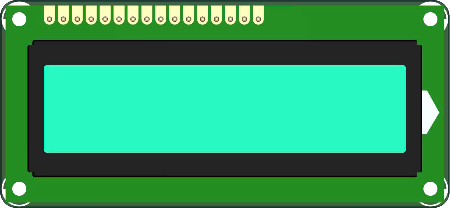
The MKEM0007 LCD1602 module, manufactured by MKEVN, is a 16x2 character display module based on the HD44780 controller. It is capable of displaying up to 32 characters (16 characters per line across 2 lines) and is widely used in embedded systems for creating user interfaces. This module is ideal for applications requiring a simple and efficient way to display text, numeric data, or status messages.
Explore Projects Built with mkem0007_lcd1602_module
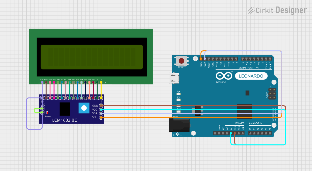
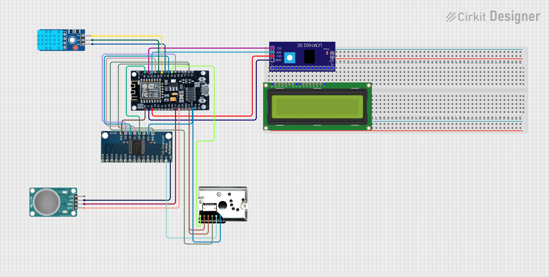
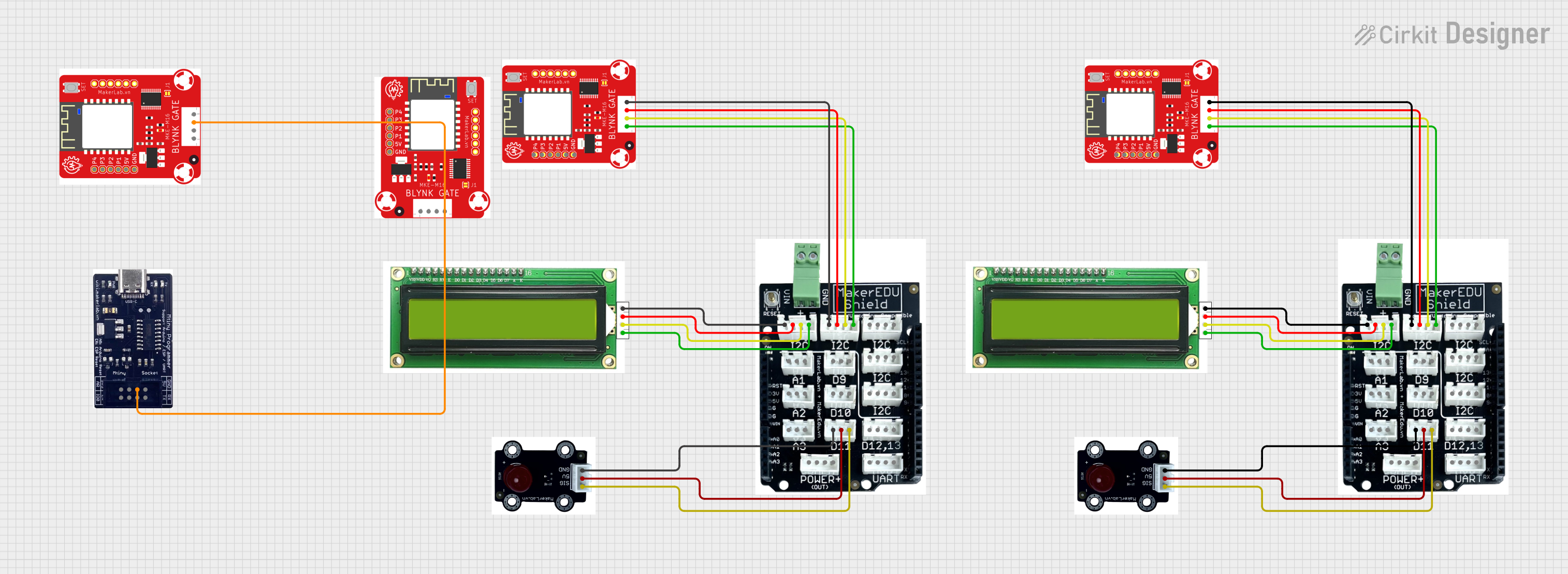
Explore Projects Built with mkem0007_lcd1602_module
Common Applications and Use Cases
- Microcontroller-based projects (e.g., Arduino, Raspberry Pi)
- Home automation systems
- Industrial control panels
- Educational and prototyping projects
- Consumer electronics with basic text display requirements
Technical Specifications
The MKEM0007 LCD1602 module has the following key technical specifications:
| Parameter | Value |
|---|---|
| Display Type | 16x2 character LCD |
| Controller | HD44780 |
| Operating Voltage | 5V DC |
| Operating Current | 2mA (typical) |
| Backlight Voltage | 5V DC |
| Backlight Current | 120mA (typical) |
| Character Size | 5x8 dot matrix |
| Interface Type | Parallel (4-bit or 8-bit mode) |
| Dimensions | 80mm x 36mm x 12mm |
Pin Configuration and Descriptions
The MKEM0007 LCD1602 module has a 16-pin interface. The pin configuration is as follows:
| Pin | Name | Description |
|---|---|---|
| 1 | VSS | Ground (0V) |
| 2 | VDD | Power supply (5V DC) |
| 3 | VO | Contrast adjustment (connect to a potentiometer for contrast control) |
| 4 | RS | Register Select (0: Command register, 1: Data register) |
| 5 | RW | Read/Write control (0: Write, 1: Read) |
| 6 | E | Enable signal (triggers data read/write) |
| 7 | D0 | Data line 0 (used in 8-bit mode only) |
| 8 | D1 | Data line 1 (used in 8-bit mode only) |
| 9 | D2 | Data line 2 (used in 8-bit mode only) |
| 10 | D3 | Data line 3 (used in 8-bit mode only) |
| 11 | D4 | Data line 4 (used in 4-bit or 8-bit mode) |
| 12 | D5 | Data line 5 (used in 4-bit or 8-bit mode) |
| 13 | D6 | Data line 6 (used in 4-bit or 8-bit mode) |
| 14 | D7 | Data line 7 (used in 4-bit or 8-bit mode) |
| 15 | A | Backlight anode (connect to 5V through a resistor for backlight control) |
| 16 | K | Backlight cathode (connect to ground) |
Usage Instructions
How to Use the MKEM0007 LCD1602 Module in a Circuit
- Power Supply: Connect the VSS pin to ground and the VDD pin to a 5V DC power source.
- Contrast Adjustment: Connect the VO pin to the wiper of a 10kΩ potentiometer. Connect one end of the potentiometer to ground and the other to 5V. Adjust the potentiometer to set the display contrast.
- Data Interface: Choose between 4-bit or 8-bit mode:
- For 4-bit mode, connect D4-D7 to the microcontroller and leave D0-D3 unconnected.
- For 8-bit mode, connect all data pins (D0-D7) to the microcontroller.
- Control Pins: Connect the RS, RW, and E pins to the microcontroller. Typically, RW is tied to ground for write-only operation.
- Backlight: Connect the A pin to 5V through a current-limiting resistor (e.g., 220Ω) and the K pin to ground.
Important Considerations and Best Practices
- Power Supply: Ensure a stable 5V power supply to avoid flickering or malfunction.
- Contrast Adjustment: Properly adjust the potentiometer to make the characters visible without overdriving the display.
- Backlight Control: Use a resistor to limit the current through the backlight to prevent damage.
- Initialization: Follow the HD44780 initialization sequence when powering up the module.
- Noise Reduction: Use decoupling capacitors (e.g., 0.1µF) near the power pins to reduce noise.
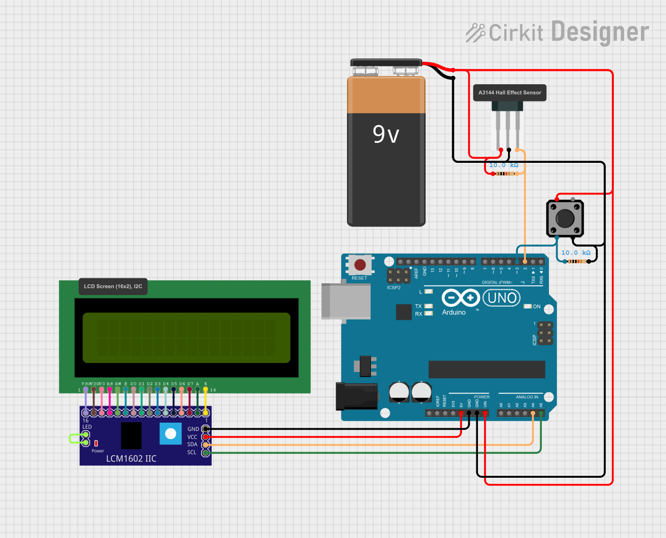
Example: Connecting to an Arduino UNO
Below is an example of how to connect and program the MKEM0007 LCD1602 module with an Arduino UNO in 4-bit mode:
Circuit Connections
| LCD Pin | Arduino Pin |
|---|---|
| VSS | GND |
| VDD | 5V |
| VO | Potentiometer (center pin) |
| RS | Pin 12 |
| RW | GND |
| E | Pin 11 |
| D4 | Pin 5 |
| D5 | Pin 4 |
| D6 | Pin 3 |
| D7 | Pin 2 |
| A | 5V (via 220Ω resistor) |
| K | GND |
Arduino Code
#include <LiquidCrystal.h>

// Initialize the library with the numbers of the interface pins
LiquidCrystal lcd(12, 11, 5, 4, 3, 2);

void setup() {
  // Set up the LCD's number of columns and rows
  lcd.begin(16, 2);

  // Print a message to the LCD
  lcd.print("Hello, World!");
}

void loop() {
  // Set the cursor to column 0, line 1 (second row)
  lcd.setCursor(0, 1);

  // Print the current time in seconds since the Arduino started
  lcd.print(millis() / 1000);
}
Troubleshooting and FAQs
Common Issues and Solutions
No Display or Blank Screen:
- Check the power connections (VSS to GND, VDD to 5V).
- Adjust the contrast using the potentiometer connected to VO.
- Ensure the backlight is properly connected (A to 5V via a resistor, K to GND).
Flickering or Unstable Display:
- Verify the power supply is stable and noise-free.
- Add decoupling capacitors (e.g., 0.1µF) near the VDD and VSS pins.
Incorrect Characters or No Response:
- Double-check the data and control pin connections.
- Ensure the correct initialization sequence is implemented in the code.
Backlight Not Working:
- Verify the current-limiting resistor is properly connected to the A pin.
- Check the polarity of the backlight connections (A to 5V, K to GND).
FAQs
Q: Can I use the MKEM0007 LCD1602 module with a 3.3V microcontroller?
A: The module is designed for 5V operation. To use it with a 3.3V microcontroller, you will need a level shifter or voltage divider for the data and control lines.
Q: How do I display custom characters?
A: The HD44780 controller supports custom characters. Use the createChar() function in the LiquidCrystal library to define and display custom characters.
Q: Can I control the backlight brightness?
A: Yes, you can use a PWM pin on your microcontroller to control the backlight brightness by connecting it to the A pin through a transistor or MOSFET.
Q: Is the module compatible with I2C?
A: The MKEM0007 LCD1602 module does not natively support I2C. However, you can use an I2C backpack module to enable I2C communication.