How to Use IR LED Board: Examples, Pinouts, and Specs
Introduction
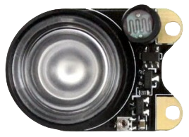
The IR LED Board by Raspberry Pi (Manufacturer Part ID: IR LED Board) is a compact circuit board equipped with infrared light-emitting diodes (LEDs). These LEDs emit light in the infrared spectrum, which is invisible to the human eye but can be detected by compatible sensors and devices. The IR LED Board is commonly used for transmitting infrared signals in applications such as remote controls, proximity sensors, and wireless communication systems.
Explore Projects Built with IR LED Board
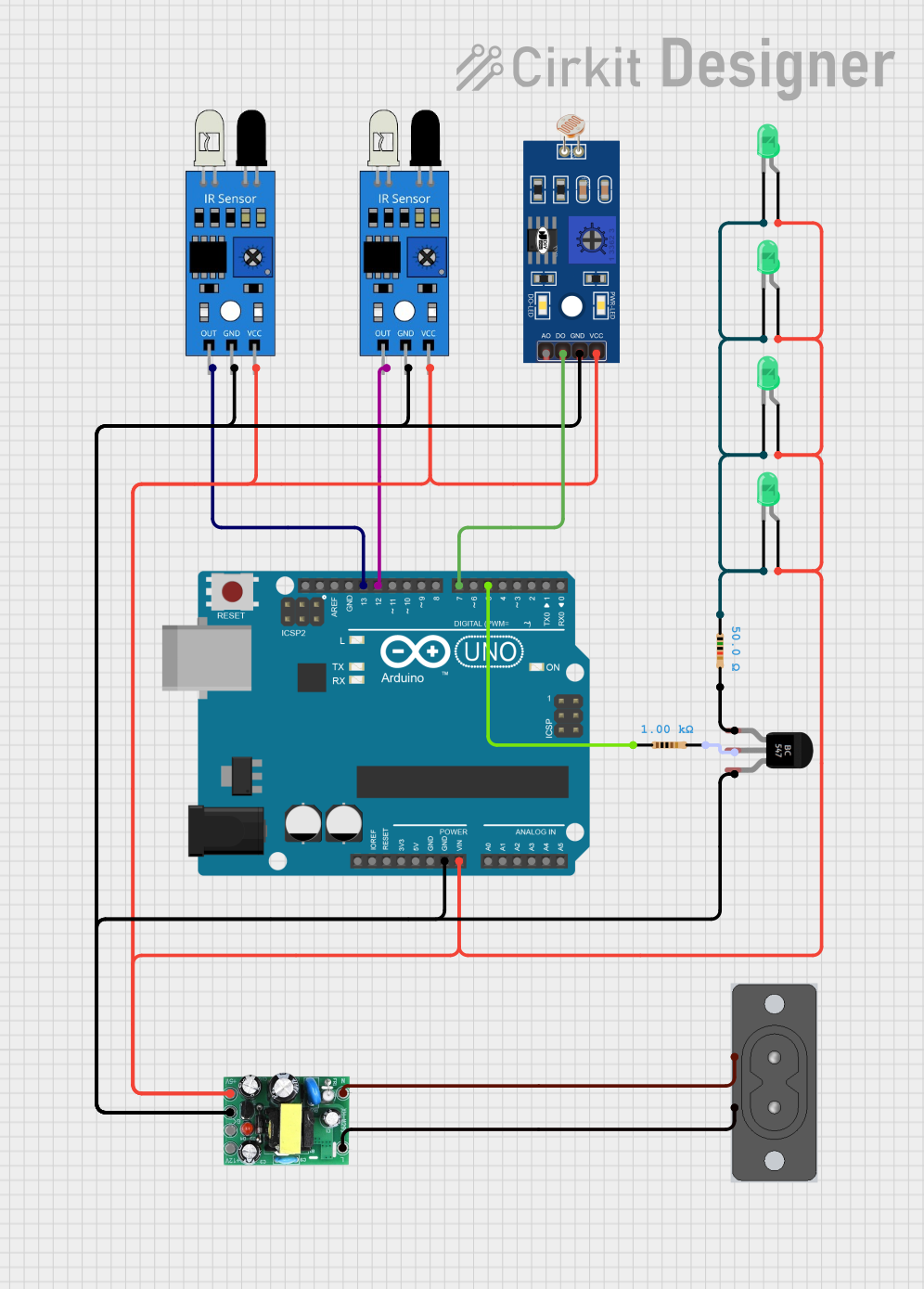
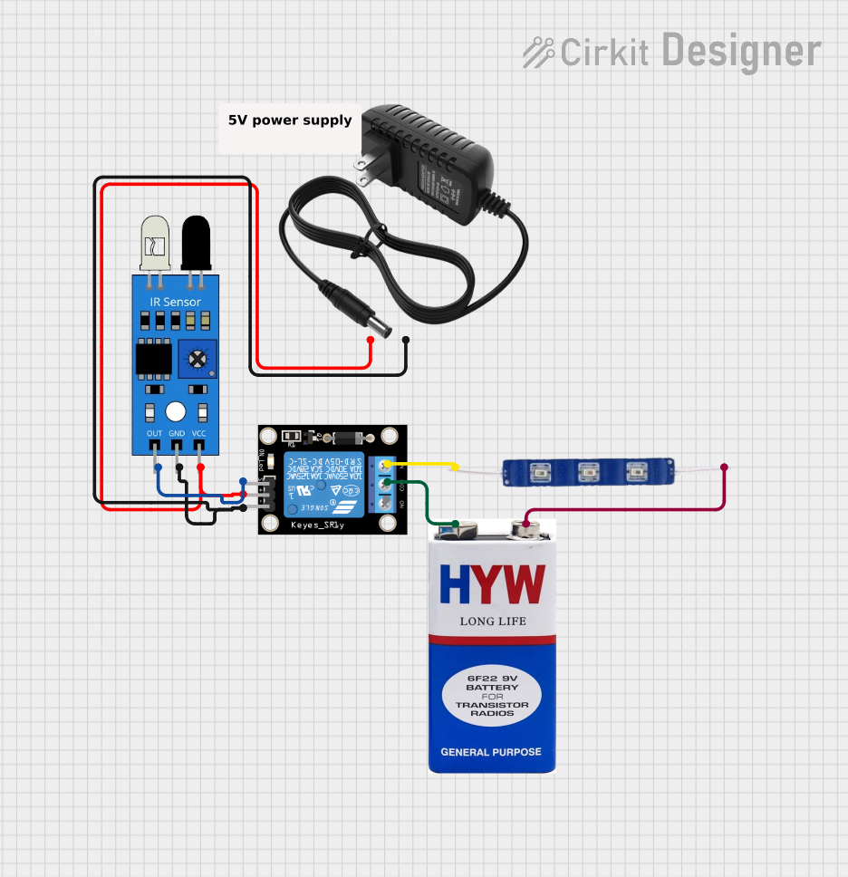
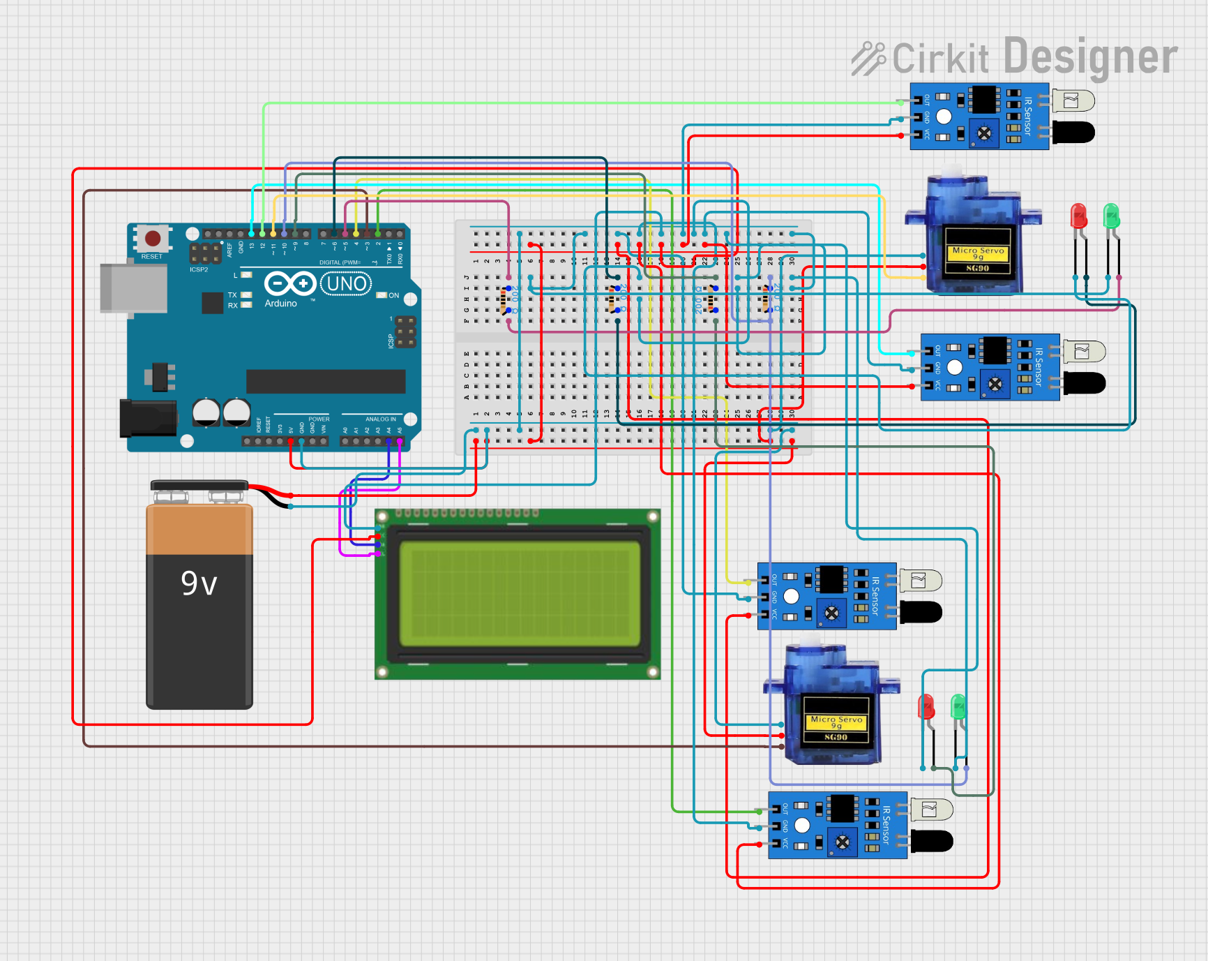
Explore Projects Built with IR LED Board
Common Applications and Use Cases
- Remote Controls: Transmitting signals to TVs, air conditioners, and other appliances.
- Proximity Sensors: Detecting objects or obstacles in robotics and automation.
- Data Communication: Enabling wireless data transfer between devices.
- Night Vision Systems: Providing illumination for cameras in low-light or no-light conditions.
Technical Specifications
The following table outlines the key technical details of the IR LED Board:
| Parameter | Value |
|---|---|
| Manufacturer | Raspberry Pi |
| Part ID | IR LED Board |
| Operating Voltage | 3.3V to 5V |
| Current Consumption | 20mA (typical per LED) |
| Wavelength | 850nm to 950nm (infrared spectrum) |
| Number of LEDs | 2 to 4 (depending on the model) |
| Beam Angle | 20° to 30° |
| Dimensions | 25mm x 25mm x 5mm |
Pin Configuration and Descriptions
The IR LED Board typically has a 3-pin interface for easy integration into circuits. The pin configuration is as follows:
| Pin | Name | Description |
|---|---|---|
| 1 | VCC | Power supply input (3.3V to 5V). |
| 2 | GND | Ground connection. |
| 3 | Signal | Input signal to control the IR LEDs (active HIGH). |
Usage Instructions
How to Use the IR LED Board in a Circuit
- Power Connection: Connect the VCC pin to a 3.3V or 5V power source and the GND pin to the ground of your circuit.
- Signal Input: Use a microcontroller (e.g., Raspberry Pi or Arduino UNO) to send a HIGH signal to the Signal pin. This will activate the IR LEDs.
- Resistor Selection: If not already included on the board, use a current-limiting resistor (typically 220Ω to 330Ω) in series with the VCC pin to prevent overcurrent damage to the LEDs.
Important Considerations and Best Practices
- Power Supply: Ensure the power supply voltage matches the board's operating range (3.3V to 5V).
- Signal Timing: For communication applications, use a modulated signal (e.g., 38kHz) to improve signal reliability and reduce interference.
- Heat Management: Avoid prolonged activation of the IR LEDs at maximum current to prevent overheating.
- Line of Sight: For optimal performance, ensure a clear line of sight between the IR LED Board and the receiving device.
Example: Using the IR LED Board with Arduino UNO
Below is an example of how to control the IR LED Board using an Arduino UNO:
// Example: Controlling the IR LED Board with Arduino UNO
// Connect the Signal pin of the IR LED Board to Arduino pin 9

const int irLedPin = 9; // Define the pin connected to the IR LED Board

void setup() {
  pinMode(irLedPin, OUTPUT); // Set the IR LED pin as an output
}

void loop() {
  digitalWrite(irLedPin, HIGH); // Turn on the IR LEDs
  delay(1000);                  // Keep the LEDs on for 1 second
  digitalWrite(irLedPin, LOW);  // Turn off the IR LEDs
  delay(1000);                  // Keep the LEDs off for 1 second
}
Troubleshooting and FAQs
Common Issues and Solutions
IR LEDs Not Turning On:
- Cause: Incorrect power supply or loose connections.
- Solution: Verify that the VCC and GND pins are properly connected and the power supply voltage is within the specified range.
Weak or No Signal Detected:
- Cause: Misalignment between the IR LED Board and the receiver.
- Solution: Ensure a clear line of sight and adjust the board's orientation for better alignment.
Overheating of LEDs:
- Cause: Excessive current through the LEDs.
- Solution: Use appropriate current-limiting resistors if not already included on the board.
Interference with Other Devices:
- Cause: Unmodulated or continuous IR signal.
- Solution: Use a modulated signal (e.g., 38kHz) for communication to reduce interference.
FAQs
Q1: Can the IR LED Board be used with a 12V power supply?
A1: No, the IR LED Board is designed to operate within a voltage range of 3.3V to 5V. Using a 12V power supply may damage the board.
Q2: How far can the IR LED Board transmit signals?
A2: The transmission range depends on factors such as the number of LEDs, power supply, and environmental conditions. Typically, the range is 5 to 10 meters in indoor environments.
Q3: Can the IR LED Board be used for night vision cameras?
A3: Yes, the IR LED Board can provide infrared illumination for night vision cameras, but ensure the wavelength matches the camera's sensitivity.
Q4: Is the board compatible with Raspberry Pi?
A4: Yes, the IR LED Board can be directly connected to Raspberry Pi GPIO pins for control and signal modulation.