How to Use 74HC00: Examples, Pinouts, and Specs
Introduction
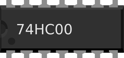
The 74HC00 is a quad 2-input NAND gate integrated circuit (IC) that is part of the 74HC family of digital logic chips. This IC contains four independent NAND gates, each of which can be used to perform the basic NAND logic function on two separate inputs. NAND gates are fundamental building blocks in digital electronics, used in various applications such as logic gate circuits, computing, signal processing, and more.
Common applications of the 74HC00 include:
- Logic gate circuits and combinational logic
- Building blocks for more complex logic functions
- Signal gating and control
- Oscillator circuits
- Pulse shaping and timing applications
Explore Projects Built with 74HC00

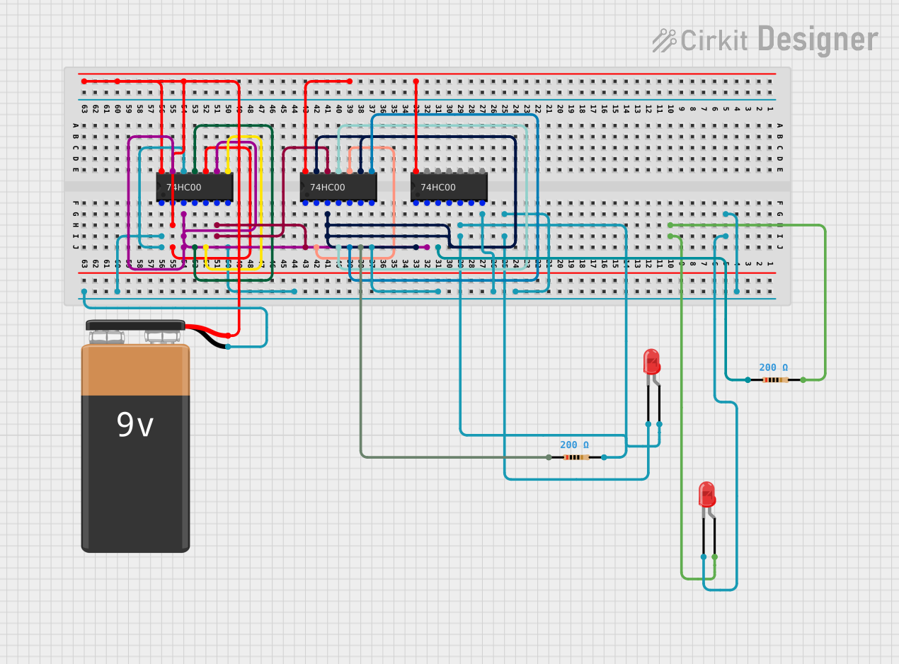

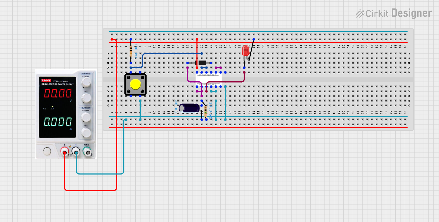
Explore Projects Built with 74HC00
Technical Specifications
Key Technical Details
- Supply Voltage (Vcc): 2.0V to 6.0V
- Input Voltage (Vin): 0V to Vcc
- Output Voltage (Vout): 0V to Vcc
- High-Level Input Voltage (VIH): Minimum 2V
- Low-Level Input Voltage (VIL): Maximum 0.8V
- High-Level Output Current (IOH): -5.2 mA (max)
- Low-Level Output Current (IOL): 5.2 mA (max)
- Propagation Delay Time: Approx. 8ns (Vcc = 4.5V)
- Operating Temperature Range: -40°C to +125°C
Pin Configuration and Descriptions
| Pin Number | Name | Description |
|---|---|---|
| 1 | 1A | Input A for Gate 1 |
| 2 | 1B | Input B for Gate 1 |
| 3 | 1Y | Output Y for Gate 1 |
| 4 | 2Y | Output Y for Gate 2 |
| 5 | 2A | Input A for Gate 2 |
| 6 | 2B | Input B for Gate 2 |
| 7 | GND | Ground (0V) |
| 8 | 3A | Input A for Gate 3 |
| 9 | 3B | Input B for Gate 3 |
| 10 | 3Y | Output Y for Gate 3 |
| 11 | 4Y | Output Y for Gate 4 |
| 12 | 4A | Input A for Gate 4 |
| 13 | 4B | Input B for Gate 4 |
| 14 | Vcc | Positive Supply Voltage |
Usage Instructions
How to Use the 74HC00 in a Circuit
Power Supply Connection: Connect pin 14 (Vcc) to the positive supply voltage (2.0V to 6.0V) and pin 7 (GND) to the ground.
Input Connection: Apply the logic signals to the input pins (1A, 1B, 2A, 2B, 3A, 3B, 4A, 4B) as required for your logic circuit.
Output Connection: Connect the output pins (1Y, 2Y, 3Y, 4Y) to the next stage of your circuit or to the input of another logic gate.
Unused Inputs: It is good practice to connect unused inputs to the ground to avoid floating inputs which can lead to unpredictable behavior.
Important Considerations and Best Practices
- Ensure that the supply voltage does not exceed the maximum rating of 6V to prevent damage to the IC.
- Avoid applying voltages to inputs when the chip is not powered, as this can cause current to flow into the device and potentially damage it.
- Decoupling capacitors (typically 0.1 µF) should be placed close to the Vcc pin to filter out noise and provide a stable power supply.
- Use pull-up or pull-down resistors if inputs are driven by mechanical switches to ensure defined logic levels when the switch is open.
Troubleshooting and FAQs
Common Issues
- Outputs not functioning as expected: Verify that all inputs are connected correctly and that the supply voltage is within the specified range.
- IC getting hot: This could be due to overvoltage or a short circuit. Immediately disconnect the power and check the circuit for errors.
Solutions and Tips for Troubleshooting
- Double-check the orientation of the IC in the circuit to ensure that the pinout matches the schematic.
- Measure the supply voltage and input signals with a multimeter to ensure they are within the specified range.
- Inspect the circuit for any solder bridges or loose connections that could cause a short circuit.
FAQs
Q: Can I replace the 74HC00 with another NAND gate IC? A: Yes, you can replace it with another NAND gate IC, but ensure that the replacement has a matching pinout and can operate within the same voltage and current specifications.
Q: What happens if I leave the inputs of the 74HC00 floating? A: Floating inputs can pick up noise and cause the output to switch erratically. It is recommended to tie unused inputs to a defined logic level.
Q: Is the 74HC00 compatible with TTL logic levels? A: The 74HC00 is a CMOS device and has different voltage levels compared to TTL. However, it is often compatible with TTL levels when operating at 5V.
Example Code for Arduino UNO
The following example demonstrates how to use one of the NAND gates of the 74HC00 with an Arduino UNO. The code will simulate a simple logic operation where the output of the NAND gate is read by the Arduino and sent to the serial monitor.
// Define the Arduino pin numbers for the inputs and output
const int inputPinA = 2;
const int inputPinB = 3;
const int outputPin = 4;

void setup() {
  // Initialize the input pins as outputs from the Arduino
  pinMode(inputPinA, OUTPUT);
  pinMode(inputPinB, OUTPUT);

  // Initialize the output pin as an input to the Arduino
  pinMode(outputPin, INPUT);

  // Begin serial communication at 9600 baud rate
  Serial.begin(9600);
}

void loop() {
  // Set both inputs to HIGH and read the output
  digitalWrite(inputPinA, HIGH);
  digitalWrite(inputPinB, HIGH);
  Serial.print("NAND Output with HIGH-HIGH input: ");
  Serial.println(digitalRead(outputPin)); // Should be LOW

  // Set one input to LOW and read the output
  digitalWrite(inputPinA, LOW);
  Serial.print("NAND Output with LOW-HIGH input: ");
  Serial.println(digitalRead(outputPin)); // Should be HIGH

  // Set the other input to LOW and read the output
  digitalWrite(inputPinB, LOW);
  Serial.print("NAND Output with LOW-LOW input: ");
  Serial.println(digitalRead(outputPin)); // Should be HIGH

  // Wait for a second before repeating the loop
  delay(1000);
}
This code sets up the Arduino to output logic levels to two inputs of a NAND gate on the 74HC00 and reads the result from the output. The results are then printed to the serial monitor. Remember to connect the Arduino pins to the corresponding input and output pins of the 74HC00, and provide the IC with an appropriate power supply.