How to Use RD-03D: Examples, Pinouts, and Specs
Introduction
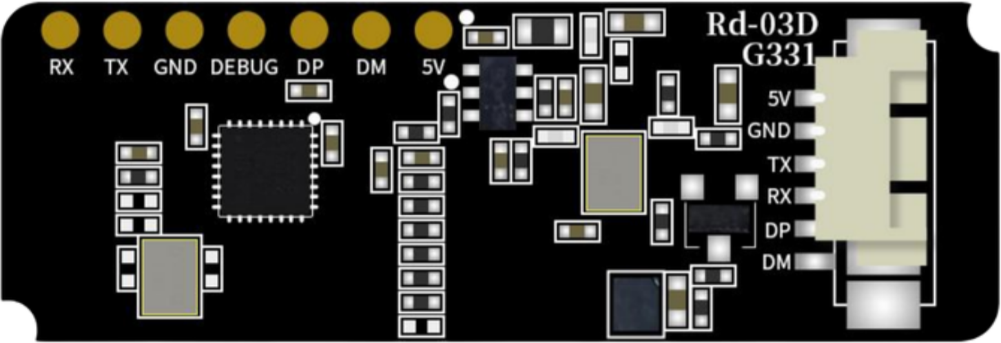
The RD-03D, manufactured by Ai Thinker, is a resistor network designed to provide multiple resistive paths in a compact package. This component is commonly used in applications requiring signal conditioning, voltage division, or pull-up/pull-down resistor configurations. Its small form factor and integrated design make it ideal for space-constrained circuits, reducing the need for multiple discrete resistors.
Explore Projects Built with RD-03D
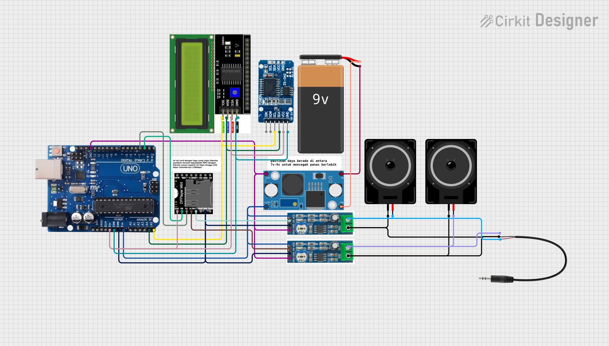

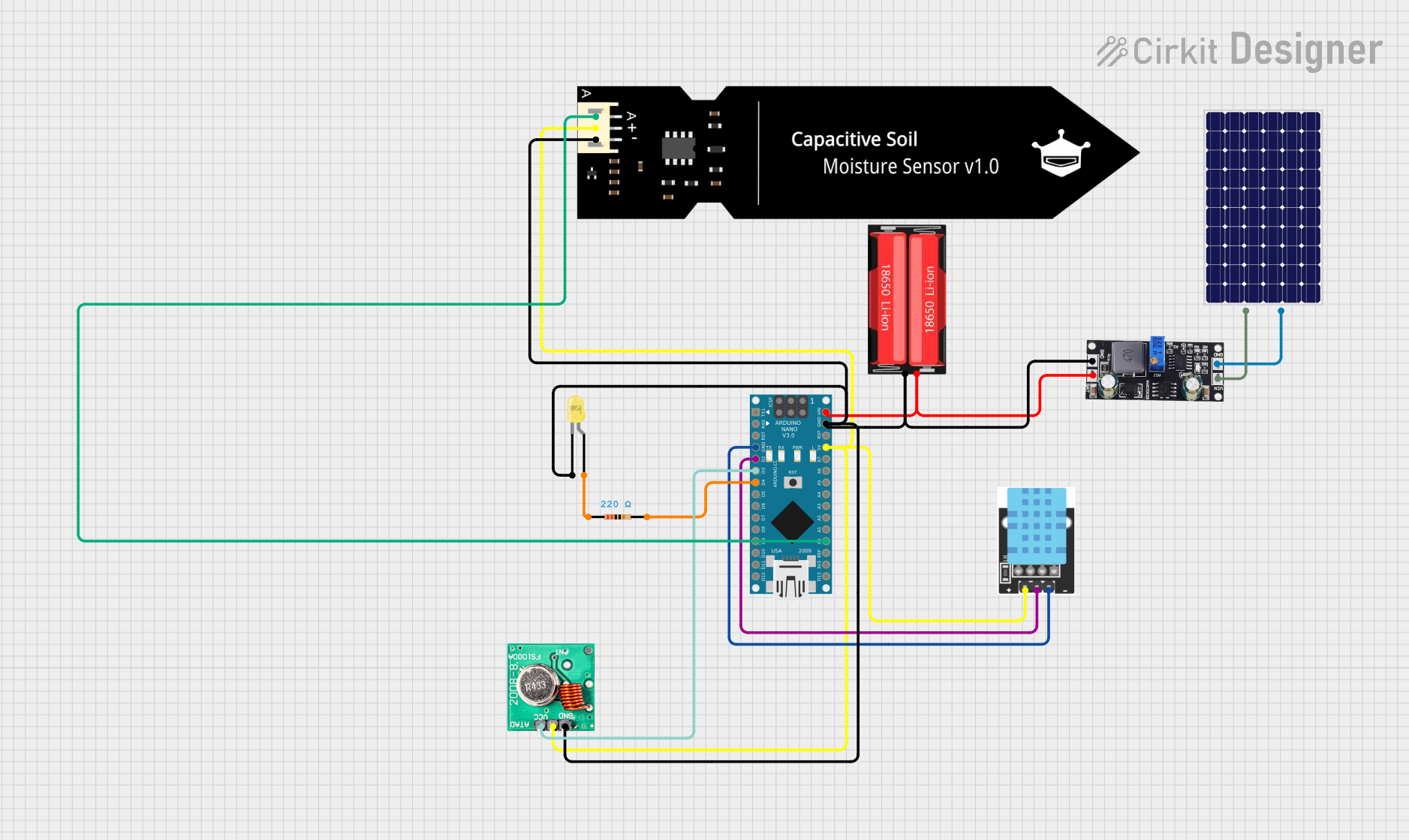
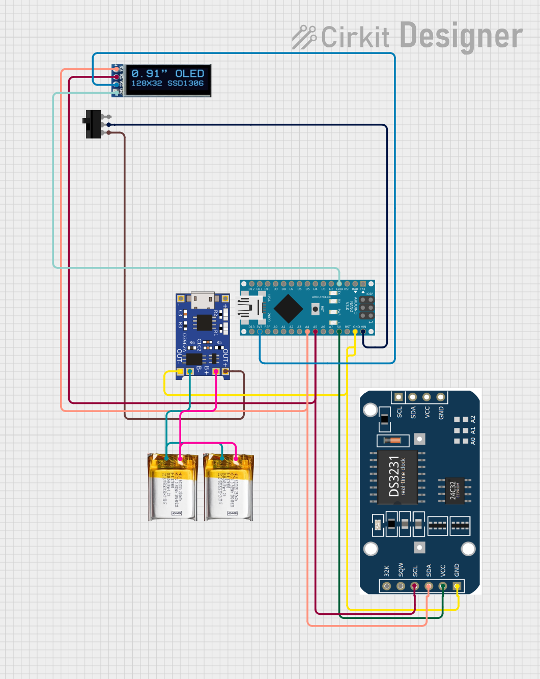
Explore Projects Built with RD-03D
Common Applications
- Signal conditioning in analog and digital circuits
- Voltage divider networks
- Pull-up or pull-down resistor arrays
- Impedance matching in communication circuits
- Noise suppression in sensitive signal lines
Technical Specifications
The RD-03D resistor network is designed to simplify circuit design by integrating multiple resistors into a single package. Below are its key technical specifications:
| Parameter | Value |
|---|---|
| Resistance Value | 10 kΩ (typical, per resistor) |
| Tolerance | ±5% |
| Number of Resistors | 4 |
| Configuration | Common pin (shared ground or Vcc) |
| Maximum Voltage | 50 V |
| Power Rating (per resistor) | 0.125 W (1/8 W) |
| Operating Temperature | -40°C to +125°C |
| Package Type | SIP-5 (Single Inline Package) |
Pin Configuration
The RD-03D features a 5-pin SIP package with the following pinout:
| Pin Number | Description |
|---|---|
| 1 | Resistor 1 terminal |
| 2 | Resistor 2 terminal |
| 3 | Resistor 3 terminal |
| 4 | Resistor 4 terminal |
| 5 | Common terminal (shared ground/Vcc) |
Usage Instructions
How to Use the RD-03D in a Circuit
- Determine the Configuration: Decide whether the common terminal (Pin 5) will be connected to ground or Vcc, depending on your circuit requirements.
- Connect the Resistors: Use the individual resistor terminals (Pins 1–4) to connect to the desired points in your circuit. For example:
- For a pull-up configuration, connect Pin 5 to Vcc and the resistor terminals to the signal lines.
- For a pull-down configuration, connect Pin 5 to ground and the resistor terminals to the signal lines.
- Verify Voltage and Power Ratings: Ensure that the applied voltage does not exceed 50 V and that the power dissipation per resistor remains within the 0.125 W limit.
Important Considerations
- Avoid Overloading: Exceeding the power rating or voltage limit can damage the resistor network.
- Minimize Noise: Place the RD-03D close to the signal lines to reduce noise and improve performance.
- Check Tolerance: The ±5% tolerance may affect precision in sensitive applications; consider this during design.
Example: Using RD-03D with an Arduino UNO
The RD-03D can be used as a pull-up resistor network for multiple input pins on an Arduino UNO. Below is an example circuit and code:
Circuit Setup
- Connect Pin 5 of the RD-03D to the 5V pin on the Arduino UNO.
- Connect Pins 1–4 to digital input pins (e.g., D2, D3, D4, D5) on the Arduino UNO.
- Connect the other ends of the input pins to push buttons, with the other side of the buttons connected to ground.
Arduino Code
// Define the input pins connected to the RD-03D resistor network
const int buttonPins[] = {2, 3, 4, 5}; // Digital pins D2 to D5

void setup() {
  // Initialize the input pins with pull-up resistors
  for (int i = 0; i < 4; i++) {
    pinMode(buttonPins[i], INPUT_PULLUP);
  }
  Serial.begin(9600); // Start serial communication for debugging
}

void loop() {
  // Read the state of each button and print it to the Serial Monitor
  for (int i = 0; i < 4; i++) {
    int buttonState = digitalRead(buttonPins[i]);
    Serial.print("Button ");
    Serial.print(i + 1);
    Serial.print(": ");
    Serial.println(buttonState == LOW ? "Pressed" : "Released");
  }
  delay(500); // Add a delay for readability
}
Troubleshooting and FAQs
Common Issues
Incorrect Resistance Values
- Cause: Manufacturing tolerance or incorrect measurement technique.
- Solution: Verify the resistance using a multimeter and account for the ±5% tolerance.
Overheating
- Cause: Exceeding the power rating of 0.125 W per resistor.
- Solution: Reduce the current through the resistor or use a higher-rated resistor network.
Signal Noise
- Cause: Long traces or improper placement of the RD-03D.
- Solution: Place the resistor network closer to the signal source and use proper grounding techniques.
FAQs
Q: Can I use the RD-03D for high-frequency signals?
A: The RD-03D is suitable for low- to mid-frequency applications. For high-frequency signals, consider resistor networks with lower parasitic capacitance.
Q: What happens if I exceed the voltage rating?
A: Exceeding the 50 V maximum voltage can cause permanent damage to the resistor network and may lead to circuit failure.
Q: Can I use the RD-03D with fewer than 4 resistors?
A: Yes, you can leave unused resistor terminals unconnected without affecting the performance of the other resistors.
By following this documentation, you can effectively integrate the RD-03D resistor network into your electronic designs.