How to Use RELAY 5 PIN: Examples, Pinouts, and Specs

Introduction
The RELAY 5 PIN, manufactured by DEWA with part ID AUDI VARIASI, is an electromechanical switch designed to control high-power circuits using low-power signals. This component provides electrical isolation between the control circuit and the load circuit, ensuring safe and efficient operation. It is widely used in automotive, industrial, and home automation applications.
Explore Projects Built with RELAY 5 PIN


Explore Projects Built with RELAY 5 PIN
Common Applications
- Automotive systems (e.g., controlling headlights, horns, or fuel pumps)
- Home automation (e.g., switching appliances or lighting)
- Industrial control systems
- Microcontroller-based projects (e.g., Arduino or Raspberry Pi)
Technical Specifications
The following table outlines the key technical details of the RELAY 5 PIN:
| Parameter | Value |
|---|---|
| Manufacturer | DEWA |
| Part ID | AUDI VARIASI |
| Coil Voltage | 12V DC |
| Coil Resistance | 160 Ω |
| Contact Rating | 30A at 250V AC / 30V DC |
| Contact Configuration | SPDT (Single Pole Double Throw) |
| Operating Temperature | -40°C to +85°C |
| Dimensions | 28mm x 28mm x 25mm |
| Weight | 30g |
Pin Configuration
The RELAY 5 PIN has the following pinout:
| Pin Number | Name | Description |
|---|---|---|
| 1 | Coil (+) | Positive terminal of the relay coil. Connect to the control signal (e.g., 12V). |
| 2 | Coil (-) | Negative terminal of the relay coil. Connect to ground. |
| 3 | Common (COM) | Common terminal for the load circuit. |
| 4 | Normally Open (NO) | Open when the relay is inactive; closes when the relay is activated. |
| 5 | Normally Closed (NC) | Closed when the relay is inactive; opens when the relay is activated. |
Usage Instructions
How to Use the RELAY 5 PIN in a Circuit
Connect the Coil Terminals:
- Connect pin 1 (Coil +) to the control signal (e.g., 12V from a microcontroller or power source).
- Connect pin 2 (Coil -) to ground.
Connect the Load Circuit:
- Connect the load's power source to pin 3 (COM).
- Connect the load to either pin 4 (NO) or pin 5 (NC), depending on the desired behavior:
- Use pin 4 (NO) if the load should be powered only when the relay is activated.
- Use pin 5 (NC) if the load should be powered when the relay is inactive.
Activate the Relay:
- Apply the appropriate voltage (e.g., 12V) to the coil terminals to activate the relay.
- When activated, the relay switches the connection between COM and NO.
Important Considerations
- Diode Protection: Always connect a flyback diode across the coil terminals to protect the circuit from voltage spikes when the relay is deactivated.
- Power Ratings: Ensure the load does not exceed the relay's contact rating (30A at 250V AC or 30V DC).
- Isolation: Use optocouplers or transistors to drive the relay if the control circuit cannot directly supply the required current.
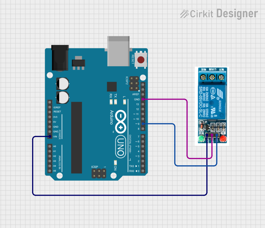
Example: Using the RELAY 5 PIN with an Arduino UNO
Below is an example of how to control the RELAY 5 PIN using an Arduino UNO:
// Define the pin connected to the relay's coil
const int relayPin = 7;

void setup() {
  // Set the relay pin as an output
  pinMode(relayPin, OUTPUT);

  // Ensure the relay is off at startup
  digitalWrite(relayPin, LOW);
}

void loop() {
  // Turn the relay on
  digitalWrite(relayPin, HIGH);
  delay(5000); // Keep the relay on for 5 seconds

  // Turn the relay off
  digitalWrite(relayPin, LOW);
  delay(5000); // Keep the relay off for 5 seconds
}
Note:
- Use a transistor (e.g., 2N2222) to drive the relay if the Arduino cannot supply enough current.
- Place a flyback diode (e.g., 1N4007) across the relay coil to protect the Arduino from voltage spikes.
Troubleshooting and FAQs
Common Issues and Solutions
Relay Not Activating:
- Cause: Insufficient voltage or current to the coil.
- Solution: Verify the control signal voltage and current. Ensure it matches the relay's coil specifications (12V DC, 160 Ω).
Load Not Switching:
- Cause: Incorrect wiring of the load circuit.
- Solution: Double-check the connections to COM, NO, and NC. Ensure the load is connected to the correct terminal based on the desired behavior.
Voltage Spikes Damaging the Circuit:
- Cause: Lack of a flyback diode across the coil terminals.
- Solution: Install a flyback diode (e.g., 1N4007) across the coil terminals, with the cathode connected to Coil (+).
Relay Overheating:
- Cause: Load exceeds the relay's contact rating.
- Solution: Ensure the load's current and voltage are within the relay's rated limits (30A at 250V AC or 30V DC).
FAQs
Q1: Can I use the RELAY 5 PIN with a 5V control signal?
A1: No, the RELAY 5 PIN requires a 12V DC control signal. Use a transistor or relay driver circuit to step up the control signal voltage.
Q2: Is the RELAY 5 PIN suitable for AC loads?
A2: Yes, the relay can handle AC loads up to 30A at 250V AC.
Q3: How do I know if the relay is activated?
A3: You can hear a clicking sound when the relay switches. Additionally, some relays include an LED indicator to show activation status.
Q4: Can I use the RELAY 5 PIN for switching low-power signals?
A4: While possible, it is not recommended. For low-power signals, consider using a solid-state relay or a smaller mechanical relay.