How to Use DRI0002: Examples, Pinouts, and Specs
Introduction
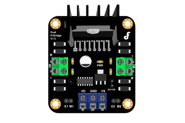
The DRI0002 is a digital relay interface module designed for controlling and monitoring relay operations in various automation systems. It acts as a bridge between digital signals and relay outputs, allowing users to control high-power electrical devices such as motors, lights, and appliances using low-power digital signals. The module is widely used in home automation, industrial control systems, and IoT applications due to its reliability and ease of integration.
Explore Projects Built with DRI0002
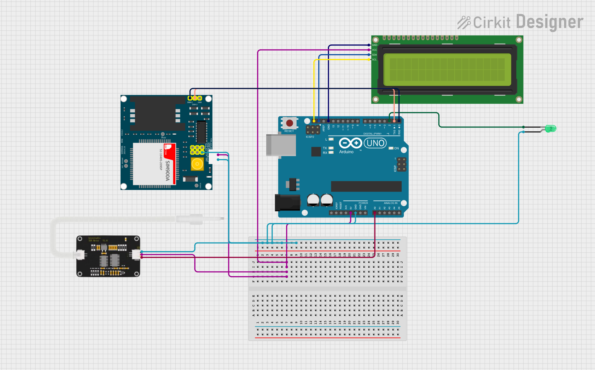
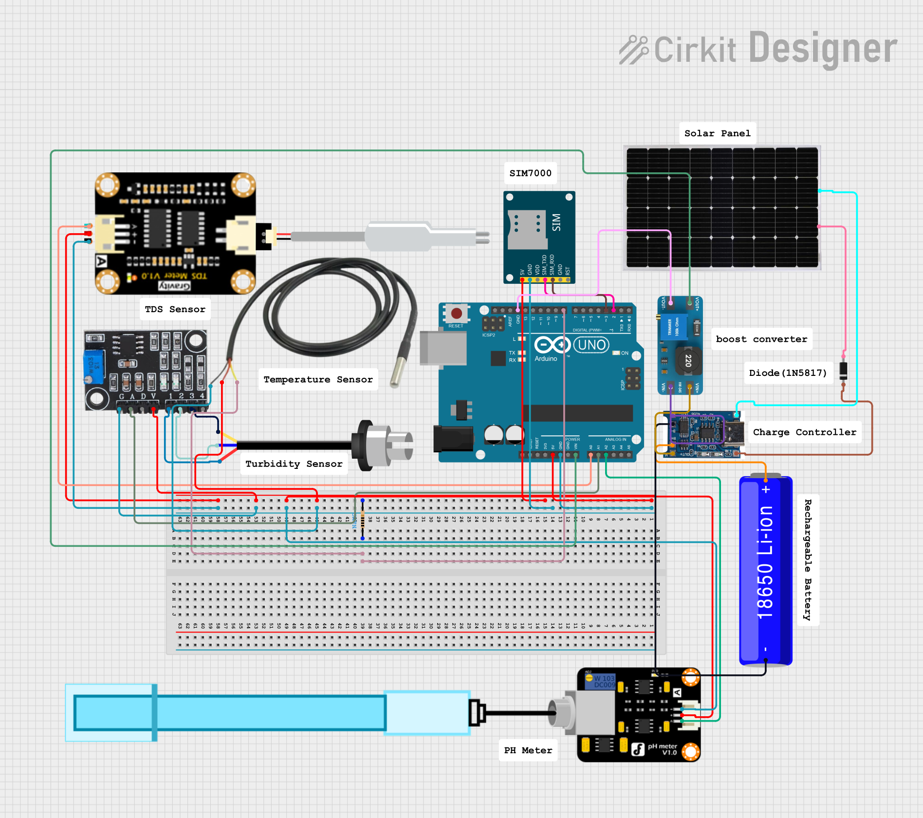

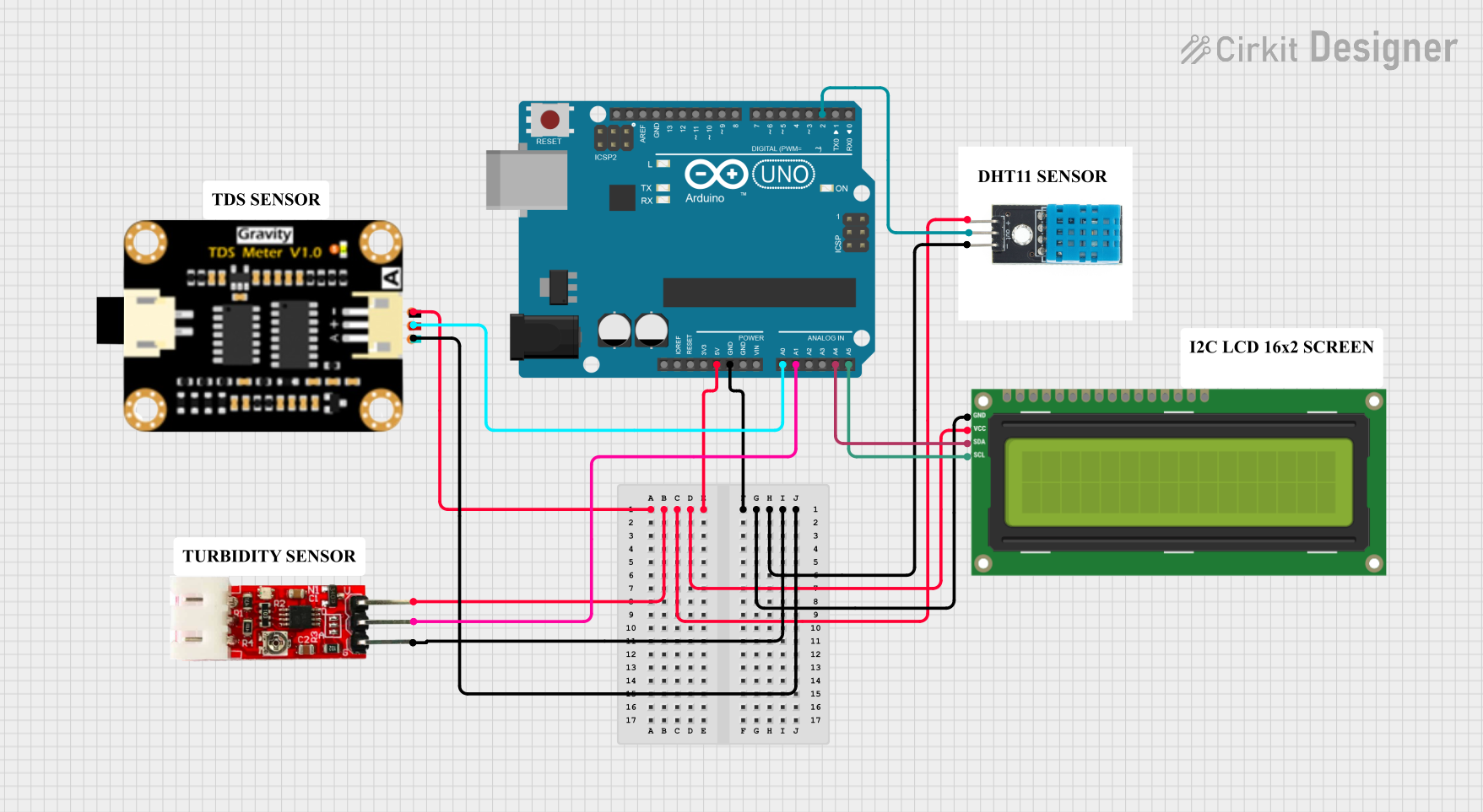
Explore Projects Built with DRI0002
Common Applications
- Home automation systems for controlling lights, fans, and other appliances.
- Industrial automation for managing motors, solenoids, and actuators.
- IoT projects requiring remote control of electrical devices.
- Robotics for switching high-power components.
- Educational projects and prototyping.
Technical Specifications
Key Technical Details
| Parameter | Value |
|---|---|
| Operating Voltage | 5V DC |
| Trigger Voltage | 3.3V to 5V DC |
| Relay Output Voltage | Up to 250V AC or 30V DC |
| Relay Output Current | Up to 10A |
| Module Dimensions | 50mm x 26mm x 18mm |
| Isolation | Optocoupler-based isolation |
| Indicator LED | Yes (Relay status indicator) |
| Mounting | PCB mount or standalone |
Pin Configuration and Descriptions
| Pin Name | Type | Description |
|---|---|---|
| VCC | Power | Connect to 5V DC power supply. |
| GND | Ground | Connect to the ground of the power supply. |
| IN | Input | Digital input signal to control the relay (3.3V to 5V logic level). |
| NO | Output | Normally Open terminal of the relay. Connect to the load for switching. |
| COM | Output | Common terminal of the relay. |
| NC | Output | Normally Closed terminal of the relay. |
Usage Instructions
How to Use the DRI0002 in a Circuit
- Power the Module: Connect the
VCCpin to a 5V DC power supply and theGNDpin to the ground. - Control Signal: Connect the
INpin to a digital output pin of a microcontroller (e.g., Arduino UNO). A HIGH signal (3.3V or 5V) will activate the relay. - Load Connection:
- Connect the load (e.g., a light bulb or motor) to the
NO(Normally Open) andCOM(Common) terminals if you want the load to be off by default and turn on when the relay is activated. - Alternatively, connect the load to the
NC(Normally Closed) andCOMterminals if you want the load to be on by default and turn off when the relay is activated.
- Connect the load (e.g., a light bulb or motor) to the
- Isolation: Ensure proper isolation between the low-voltage control side and the high-voltage load side to prevent damage to the microcontroller.
Important Considerations and Best Practices
- Power Supply: Use a stable 5V DC power supply to avoid erratic relay behavior.
- Load Ratings: Ensure the connected load does not exceed the relay's maximum voltage (250V AC or 30V DC) and current (10A).
- Optocoupler Isolation: The module includes optocoupler isolation to protect the control circuit from high-voltage spikes. However, additional protection (e.g., fuses or snubber circuits) may be required for inductive loads.
- Avoid Rapid Switching: Avoid rapidly toggling the relay to prevent wear and tear on the mechanical contacts.
Example: Connecting DRI0002 to an Arduino UNO
Below is an example of how to control the DRI0002 module using an Arduino UNO:
// Example code to control the DRI0002 relay module with an Arduino UNO

const int relayPin = 7; // Define the digital pin connected to the IN pin of DRI0002

void setup() {
  pinMode(relayPin, OUTPUT); // Set the relay pin as an output
  digitalWrite(relayPin, LOW); // Ensure the relay is off at startup
}

void loop() {
  digitalWrite(relayPin, HIGH); // Turn the relay on
  delay(1000); // Keep the relay on for 1 second
  digitalWrite(relayPin, LOW); // Turn the relay off
  delay(1000); // Keep the relay off for 1 second
}
Troubleshooting and FAQs
Common Issues and Solutions
Relay Not Activating:
- Cause: Insufficient input voltage or incorrect wiring.
- Solution: Ensure the
INpin receives a voltage between 3.3V and 5V. Check all connections.
Relay Stuck in One State:
- Cause: Faulty relay or excessive load current.
- Solution: Verify the load does not exceed the relay's maximum current rating. Replace the module if necessary.
Erratic Behavior:
- Cause: Unstable power supply or interference from high-power devices.
- Solution: Use a stable 5V DC power supply and keep the control circuit isolated from high-power devices.
LED Indicator Not Working:
- Cause: Faulty LED or insufficient input signal.
- Solution: Check the input signal voltage and ensure proper wiring.
FAQs
Q1: Can I use the DRI0002 with a 3.3V microcontroller like the ESP32?
A1: Yes, the DRI0002 is compatible with 3.3V logic levels. Ensure the IN pin receives a stable 3.3V signal.
Q2: Is the module safe for switching inductive loads like motors?
A2: Yes, but it is recommended to use a snubber circuit or flyback diode to protect the relay contacts from voltage spikes.
Q3: Can I control multiple DRI0002 modules with a single microcontroller?
A3: Yes, as long as each module is connected to a separate digital output pin and the microcontroller can handle the total current draw.
Q4: What happens if I exceed the relay's maximum ratings?
A4: Exceeding the voltage or current ratings can damage the relay and pose safety risks. Always stay within the specified limits.