How to Use TP4056 3.7V Mini - Protected Mode Type C: Examples, Pinouts, and Specs
Introduction
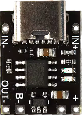
The TP4056 3.7V Mini - Protected Mode Type C, manufactured by NanJing Top Power ASIC Corp, is a compact lithium battery charger IC designed for charging single-cell lithium-ion batteries. It features a Type-C input, overcharge protection, and a built-in battery protection circuit to prevent over-discharge and short circuits. This module is widely used in portable electronics, DIY projects, and battery-powered devices due to its small size, ease of use, and robust safety features.
Explore Projects Built with TP4056 3.7V Mini - Protected Mode Type C


Explore Projects Built with TP4056 3.7V Mini - Protected Mode Type C
Common Applications
- Charging single-cell lithium-ion or lithium-polymer batteries (3.7V nominal voltage)
- Power banks and portable chargers
- Wearable devices and IoT gadgets
- DIY electronics projects
- Battery management systems for small devices
Technical Specifications
Below are the key technical details and pin configuration for the TP4056 3.7V Mini - Protected Mode Type C:
Key Technical Details
| Parameter | Value |
|---|---|
| Input Voltage Range | 4.5V to 5.5V |
| Charging Voltage | 4.2V ± 1% |
| Maximum Charging Current | 1A (adjustable via onboard resistor) |
| Battery Overcharge Protection | 4.28V ± 1% |
| Battery Over-discharge Protection | 2.5V ± 1% |
| Short Circuit Protection | Yes |
| Input Connector | USB Type-C |
| Operating Temperature Range | -10°C to +85°C |
| Dimensions | 25mm x 19mm x 5mm |
Pin Configuration and Descriptions
The TP4056 3.7V Mini - Protected Mode Type C module has the following pins:
| Pin Name | Description |
|---|---|
| IN+ | Positive input terminal (connect to 5V power source, e.g., USB Type-C) |
| IN- | Negative input terminal (connect to ground of the power source) |
| BAT+ | Positive terminal for the lithium-ion battery |
| BAT- | Negative terminal for the lithium-ion battery |
| OUT+ | Positive output terminal (connected to the load, e.g., device being powered) |
| OUT- | Negative output terminal (connected to the load ground) |
Usage Instructions
How to Use the TP4056 in a Circuit
- Power Input: Connect a 5V power source to the IN+ and IN- pins. You can use a USB Type-C cable for convenience.
- Battery Connection: Connect the lithium-ion battery to the BAT+ and BAT- pins. Ensure correct polarity to avoid damage.
- Load Connection: If you want to power a device while charging the battery, connect the device to the OUT+ and OUT- pins.
- Adjust Charging Current: The default charging current is 1A. To adjust it, replace the onboard resistor (Rprog). Use the formula: [ I_{CHG} = \frac{1200}{R_{PROG}} ] where ( R_{PROG} ) is in kΩ and ( I_{CHG} ) is in mA.
Important Considerations and Best Practices
- Battery Compatibility: Only use this module with single-cell lithium-ion or lithium-polymer batteries (nominal voltage: 3.7V).
- Heat Dissipation: The module may heat up during operation, especially at high charging currents. Ensure proper ventilation.
- Avoid Reverse Polarity: Connecting the battery or power source with reversed polarity can damage the module.
- Charging Indicator LEDs:
- Red LED: Charging in progress.
- Blue LED: Charging complete.
- Do Not Exceed Input Voltage: Ensure the input voltage does not exceed 5.5V to prevent damage.
Example: Using TP4056 with Arduino UNO
The TP4056 can be used to charge a battery that powers an Arduino UNO. Below is an example of how to monitor the battery voltage using the Arduino:
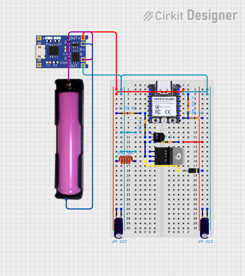
Circuit Diagram
- Connect the BAT+ and BAT- pins of the TP4056 to the battery.
- Connect the battery's positive terminal to an analog input pin (e.g., A0) on the Arduino through a voltage divider.
Arduino Code
// TP4056 Battery Voltage Monitoring with Arduino UNO
// Ensure the voltage divider reduces the battery voltage to below 5V for safe ADC input.

const int batteryPin = A0; // Analog pin connected to the voltage divider
const float voltageDividerRatio = 2.0; // Adjust based on your resistor values
const float referenceVoltage = 5.0; // Arduino UNO's ADC reference voltage

void setup() {
  Serial.begin(9600); // Initialize serial communication
}

void loop() {
  int adcValue = analogRead(batteryPin); // Read the ADC value
  float batteryVoltage = (adcValue / 1023.0) * referenceVoltage * voltageDividerRatio;

  // Print the battery voltage to the Serial Monitor
  Serial.print("Battery Voltage: ");
  Serial.print(batteryVoltage);
  Serial.println(" V");

  delay(1000); // Wait for 1 second before the next reading
}
Note: Use appropriate resistor values for the voltage divider to ensure the battery voltage is scaled down to a safe level for the Arduino's ADC input.
Troubleshooting and FAQs
Common Issues and Solutions
Module Overheating:
- Cause: High charging current or poor ventilation.
- Solution: Reduce the charging current by increasing the value of ( R_{PROG} ). Ensure proper airflow around the module.
Battery Not Charging:
- Cause: Incorrect wiring or damaged battery.
- Solution: Double-check all connections. Verify the battery's health and polarity.
No LED Indicator:
- Cause: No power input or damaged module.
- Solution: Ensure the input voltage is within the 4.5V–5.5V range. Check the power source and connections.
Short Circuit Protection Triggered:
- Cause: Output terminals are shorted.
- Solution: Disconnect the load, resolve the short circuit, and reconnect.
FAQs
Q1: Can I use the TP4056 to charge multiple batteries in series?
A1: No, the TP4056 is designed for single-cell lithium-ion batteries only. Charging multiple batteries in series requires a specialized battery management system.
Q2: How do I know when the battery is fully charged?
A2: The blue LED will light up when the battery is fully charged.
Q3: Can I use a power supply instead of a USB Type-C cable?
A3: Yes, as long as the power supply provides a stable voltage between 4.5V and 5.5V.
Q4: What happens if the input voltage exceeds 5.5V?
A4: Exceeding 5.5V can damage the module. Always use a regulated power source within the specified range.