
How to Use Module Converter Keypad Matrix 4x4 to I2C: Examples, Pinouts, and Specs
 Design with Module Converter Keypad Matrix 4x4 to I2C in Cirkit Designer
Introduction
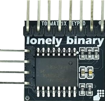
The Module Converter Keypad Matrix 4x4 to I2C is a versatile electronic component designed to simplify the process of interfacing a 4x4 matrix keypad with microcontrollers. By converting the keypad's row-column signals into I2C communication, this module reduces the number of GPIO pins required and streamlines the process of reading key presses. It is particularly useful in applications where GPIO pins are limited or where multiple devices need to communicate over the I2C bus.
Explore Projects Built with Module Converter Keypad Matrix 4x4 to I2C
 Open Project in Cirkit Designer
 Open Project in Cirkit Designer
 Open Project in Cirkit Designer
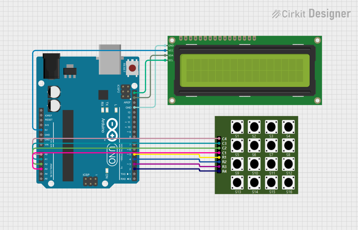 Open Project in Cirkit Designer
Explore Projects Built with Module Converter Keypad Matrix 4x4 to I2C
Open Project in Cirkit DesignerOpen Project in Cirkit DesignerOpen Project in Cirkit DesignerOpen Project in Cirkit DesignerCommon Applications and Use Cases
- Embedded systems requiring keypad input (e.g., password entry, menu navigation)
- Home automation systems
- Security systems and access control
- Industrial control panels
- Prototyping and educational projects
Technical Specifications
The following table outlines the key technical details of the module:
| Parameter | Value |
|---|---|
| Operating Voltage | 3.3V - 5V |
| Communication Protocol | I2C |
| Default I2C Address | 0x20 (configurable via jumpers) |
| Keypad Compatibility | 4x4 matrix keypad |
| Dimensions | 30mm x 25mm x 10mm |
| Operating Temperature | -20°C to 70°C |
Pin Configuration and Descriptions
The module has the following pinout:
| Pin Name | Description |
|---|---|
| VCC | Power supply input (3.3V - 5V) |
| GND | Ground connection |
| SDA | I2C data line |
| SCL | I2C clock line |
| ROW1-ROW4 | Row inputs from the 4x4 keypad |
| COL1-COL4 | Column inputs from the 4x4 keypad |
| ADDR | Optional jumper to configure the I2C address |
Usage Instructions
How to Use the Module in a Circuit
- Connect the Keypad: Attach the rows (ROW1-ROW4) and columns (COL1-COL4) of your 4x4 matrix keypad to the corresponding pins on the module.
- Power the Module: Connect the VCC pin to a 3.3V or 5V power source and the GND pin to ground.
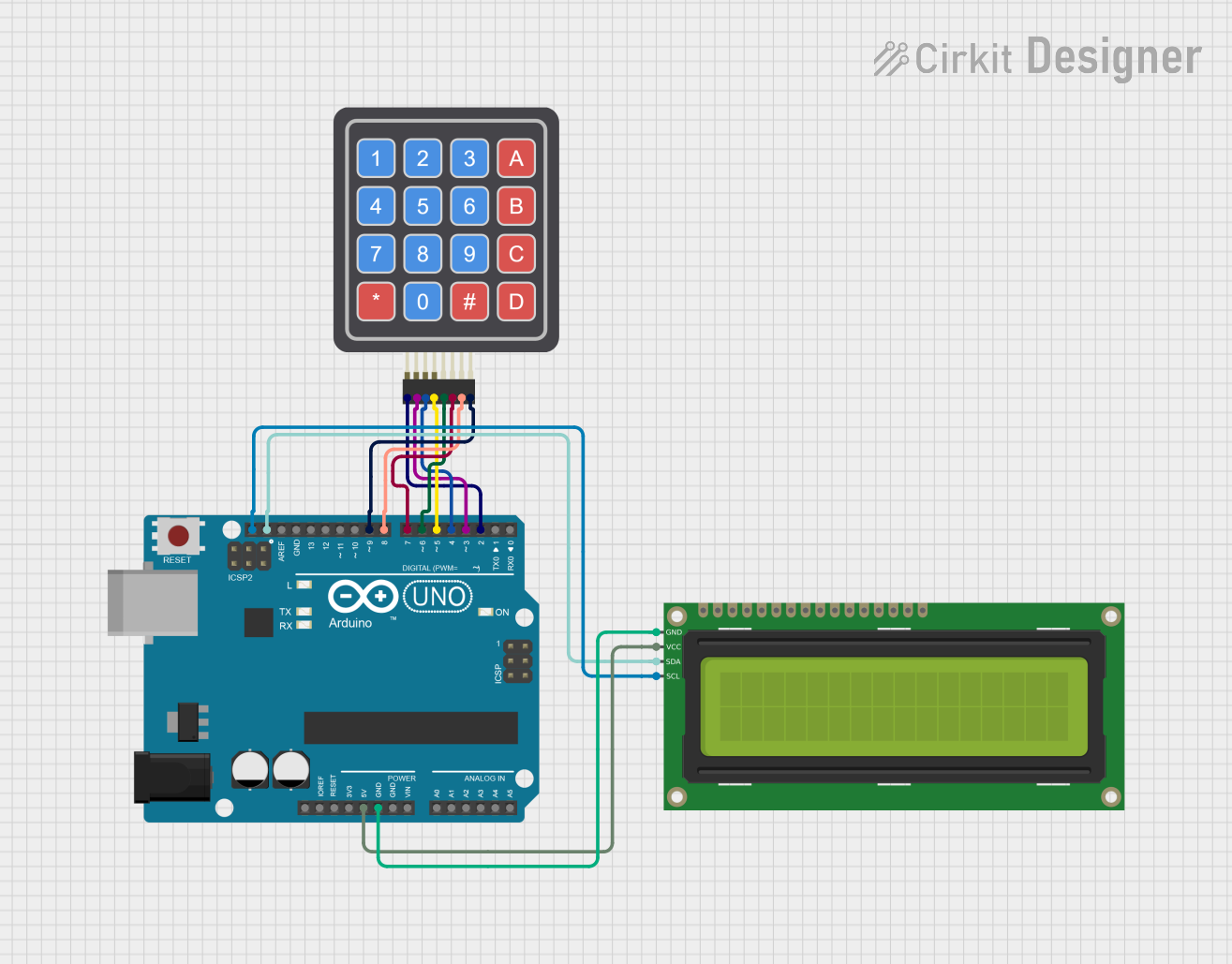
- I2C Connection: Connect the SDA and SCL pins to the corresponding I2C pins on your microcontroller (e.g., Arduino UNO: A4 for SDA, A5 for SCL).
- Address Configuration: If needed, adjust the I2C address by setting the ADDR jumper.
- Microcontroller Programming: Use an I2C library to communicate with the module and read key presses.
Important Considerations and Best Practices
- Ensure the I2C pull-up resistors are present on the SDA and SCL lines. Many microcontroller boards (e.g., Arduino UNO) include these by default.
- Avoid long wires for the I2C bus to minimize signal degradation.
- If multiple I2C devices are used, ensure each has a unique address to avoid conflicts.
- Debounce the keypad input in software to filter out false key presses caused by mechanical bouncing.
Example Code for Arduino UNO
Below is an example Arduino sketch to interface with the module:
#include <Wire.h> // Include the Wire library for I2C communication

#define I2C_ADDRESS 0x20 // Default I2C address of the module

void setup() {
  Wire.begin(); // Initialize I2C communication
  Serial.begin(9600); // Start serial communication for debugging
  Serial.println("4x4 Keypad I2C Module Initialized");
}

void loop() {
  Wire.requestFrom(I2C_ADDRESS, 1); // Request 1 byte from the module

  if (Wire.available()) {
    byte key = Wire.read(); // Read the key press data
    if (key != 0) { // Check if a key is pressed
      Serial.print("Key Pressed: ");
      Serial.println(key, HEX); // Print the key value in hexadecimal
    }
  }

  delay(100); // Small delay to avoid flooding the I2C bus
}
Troubleshooting and FAQs
Common Issues and Solutions
No Key Press Detected
- Cause: Incorrect wiring between the keypad and the module.
- Solution: Double-check the connections between the keypad rows/columns and the module pins.
I2C Communication Fails
- Cause: Incorrect I2C address or missing pull-up resistors.
- Solution: Verify the I2C address and ensure pull-up resistors are present on the SDA and SCL lines.
Multiple Key Presses Detected
- Cause: Mechanical bouncing of the keypad.
- Solution: Implement software debouncing in your microcontroller code.
Module Overheats
- Cause: Incorrect power supply voltage.
- Solution: Ensure the VCC pin is supplied with a voltage within the 3.3V - 5V range.
FAQs
Q: Can I use this module with a 3x4 keypad?
A: Yes, but only the first three columns and four rows of the module will be used. The unused pins can be left unconnected.
Q: How do I change the I2C address?
A: Adjust the ADDR jumper on the module to set a new I2C address. Refer to the module's datasheet for specific configurations.
Q: Is this module compatible with Raspberry Pi?
A: Yes, the module can be used with Raspberry Pi as it supports I2C communication. Ensure the I2C pins (SDA, SCL) are correctly connected.
Q: What happens if multiple keys are pressed simultaneously?
A: The module may not correctly register simultaneous key presses. It is designed to detect one key press at a time.