How to Use Screen Printed Electrode: Examples, Pinouts, and Specs
Introduction
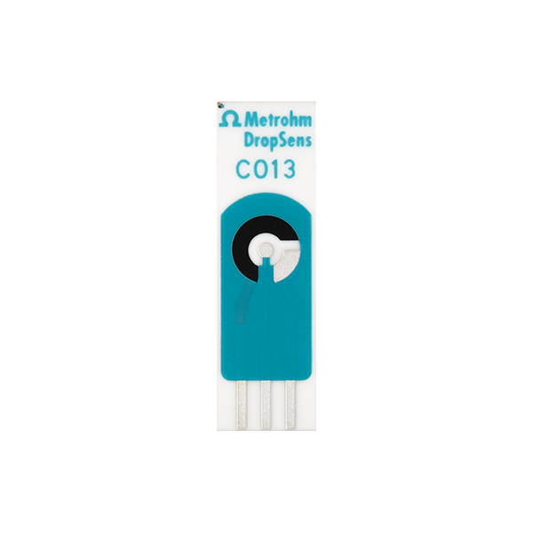
Screen Printed Electrodes (SPEs) are a type of electrode created by printing conductive materials, such as carbon, silver, or gold, onto a substrate like ceramic or plastic. These electrodes are widely used in electrochemical sensors and biosensors due to their low cost, ease of fabrication, and versatility. SPEs are ideal for applications requiring disposable or portable sensing solutions.
Explore Projects Built with Screen Printed Electrode


Explore Projects Built with Screen Printed Electrode
Common Applications and Use Cases
- Electrochemical sensing: Detection of chemical or biological analytes in solutions.
- Biosensors: Glucose monitoring, DNA detection, and enzyme-based sensors.
- Environmental monitoring: Detection of pollutants in water or air.
- Medical diagnostics: Point-of-care testing for various biomarkers.
- Food safety: Monitoring contaminants or quality indicators in food products.
Technical Specifications
Below are the general technical specifications for a typical Screen Printed Electrode. Note that specific parameters may vary depending on the manufacturer and model.
Key Technical Details
- Material: Carbon, silver, gold, or platinum (conductive ink)
- Substrate: Ceramic, plastic, or flexible polymer
- Working electrode diameter: Typically 1–4 mm
- Operating voltage range: -1.5 V to +1.5 V (varies by material)
- Operating temperature range: -10°C to +60°C
- Shelf life: Typically 6–12 months (depends on storage conditions)
Pin Configuration and Descriptions
Screen Printed Electrodes typically consist of three main electrodes: the working electrode (WE), the reference electrode (RE), and the counter electrode (CE). These are connected to a potentiostat or other measurement device.
| Pin/Connection | Description |
|---|---|
| Working Electrode (WE) | The primary electrode where the electrochemical reaction occurs. Typically made of carbon, gold, or platinum. |
| Reference Electrode (RE) | Provides a stable reference potential for accurate measurements. Often made of silver/silver chloride (Ag/AgCl). |
| Counter Electrode (CE) | Completes the circuit by allowing current to flow. Usually made of carbon or platinum. |
Usage Instructions
How to Use the Component in a Circuit
- Connect the electrodes: Attach the working, reference, and counter electrodes to the corresponding terminals of your potentiostat or measurement device.
- Prepare the sample: Place a small droplet of the solution to be tested onto the electrode surface, ensuring it covers all three electrodes.
- Run the measurement: Use the potentiostat to apply the desired voltage or current and record the resulting signal.
- Analyze the data: Interpret the electrochemical response (e.g., current or voltage) to determine the concentration of the target analyte.
Important Considerations and Best Practices
- Storage: Store SPEs in a cool, dry place to prevent degradation of the conductive material.
- Cleaning: Avoid reusing disposable SPEs. For reusable SPEs, clean the surface gently with deionized water and a soft tissue.
- Calibration: Regularly calibrate your system using standard solutions to ensure accurate measurements.
- Avoid contamination: Handle the electrodes with clean gloves to prevent contamination of the surface.
- Connection: Ensure secure and stable connections to the potentiostat to avoid signal noise.
Example: Using SPEs with Arduino UNO
Below is an example of how to interface a Screen Printed Electrode with an Arduino UNO for basic voltage measurement. Note that a signal conditioning circuit (e.g., an operational amplifier) may be required depending on the application.
// Example code for reading voltage from a Screen Printed Electrode (SPE)
// connected to an Arduino UNO analog input pin.

const int analogPin = A0; // Analog pin connected to the working electrode (WE)
float voltage = 0.0;      // Variable to store the measured voltage

void setup() {
  Serial.begin(9600); // Initialize serial communication at 9600 baud
}

void loop() {
  int sensorValue = analogRead(analogPin); // Read the analog input
  voltage = sensorValue * (5.0 / 1023.0);  // Convert ADC value to voltage
  Serial.print("Voltage: ");
  Serial.print(voltage);
  Serial.println(" V"); // Print the voltage to the Serial Monitor
  delay(1000);          // Wait for 1 second before the next reading
}
Note: This example assumes the SPE is connected to a signal conditioning circuit that outputs a voltage within the Arduino's 0–5 V input range.
Troubleshooting and FAQs
Common Issues and Solutions
No signal or weak response:
- Ensure the electrodes are properly connected to the measurement device.
- Verify that the sample solution is correctly applied and covers all three electrodes.
- Check for damage or contamination on the electrode surface.
High noise in measurements:
- Use shielded cables to reduce electromagnetic interference.
- Ensure stable connections to the potentiostat or Arduino.
- Minimize vibrations or external disturbances during measurements.
Inconsistent results:
- Calibrate the system with standard solutions before each use.
- Ensure the sample solution is well-mixed and homogeneous.
- Avoid reusing disposable SPEs, as this can lead to contamination.
FAQs
Q: Can I reuse a Screen Printed Electrode?
A: Disposable SPEs are designed for single use to ensure accuracy and prevent contamination. Reusable SPEs can be cleaned and reused, but their performance may degrade over time.
Q: What is the shelf life of an SPE?
A: The shelf life is typically 6–12 months, depending on storage conditions. Store SPEs in a cool, dry place to maximize their lifespan.
Q: Can I use SPEs for gas sensing?
A: Yes, SPEs can be modified with specific coatings or catalysts to detect gases. However, additional preparation may be required.
Q: What potentiostat should I use with SPEs?
A: Any potentiostat compatible with three-electrode systems can be used. Ensure it supports the voltage and current ranges required for your application.