How to Use Adafruit USB Boarduino: Examples, Pinouts, and Specs
Introduction
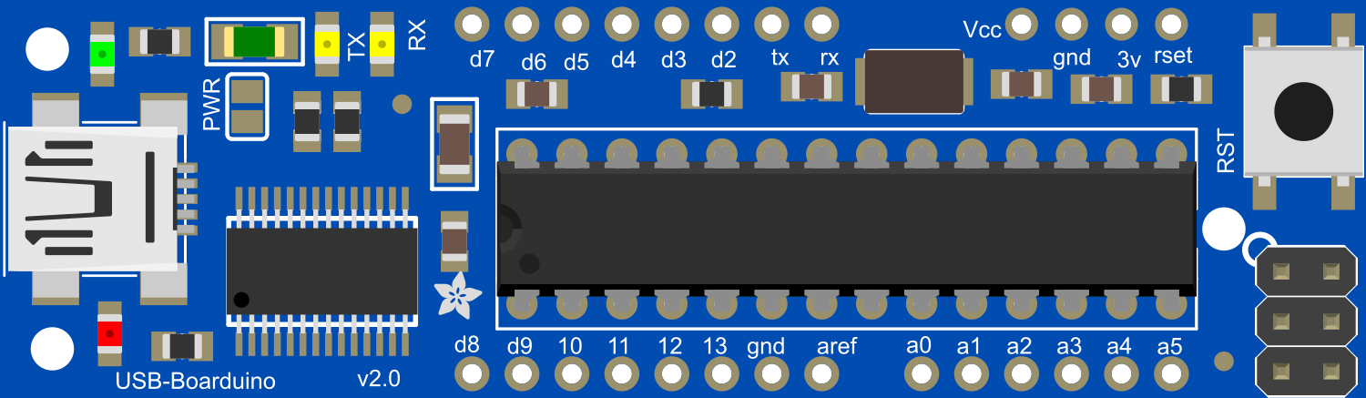
The Adafruit USB Boarduino is a versatile, breadboard-friendly development board based on the ATmega328 microcontroller. It is designed for hobbyists, educators, and professionals who need a compact, easy-to-use platform for electronic projects and prototypes. The Boarduino's USB interface simplifies programming and provides a convenient way to communicate with a computer.
Explore Projects Built with Adafruit USB Boarduino

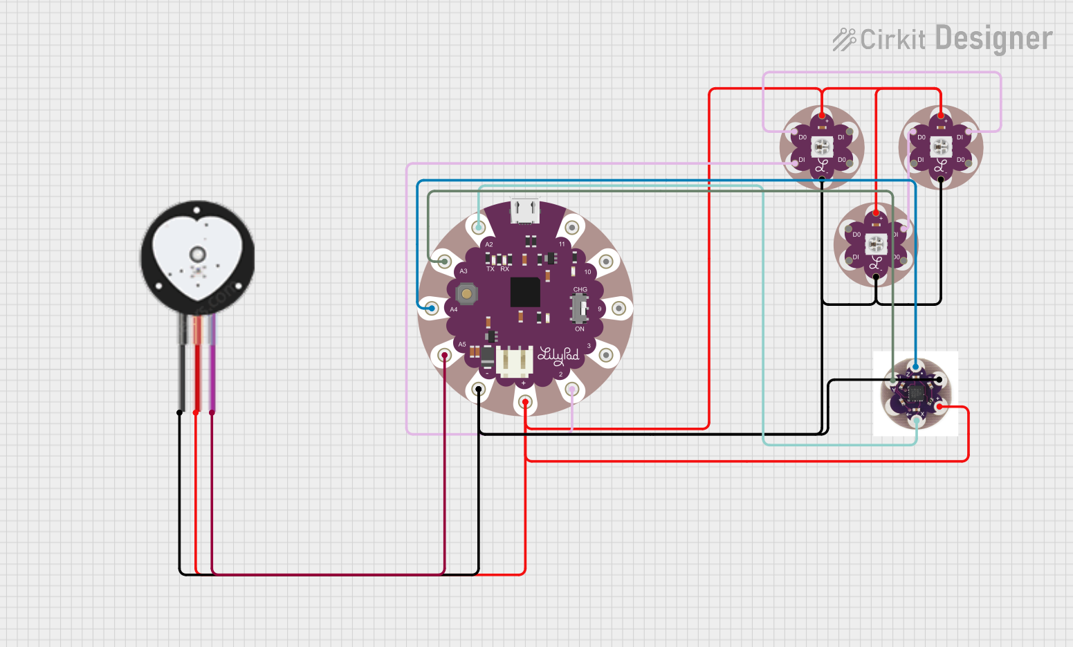

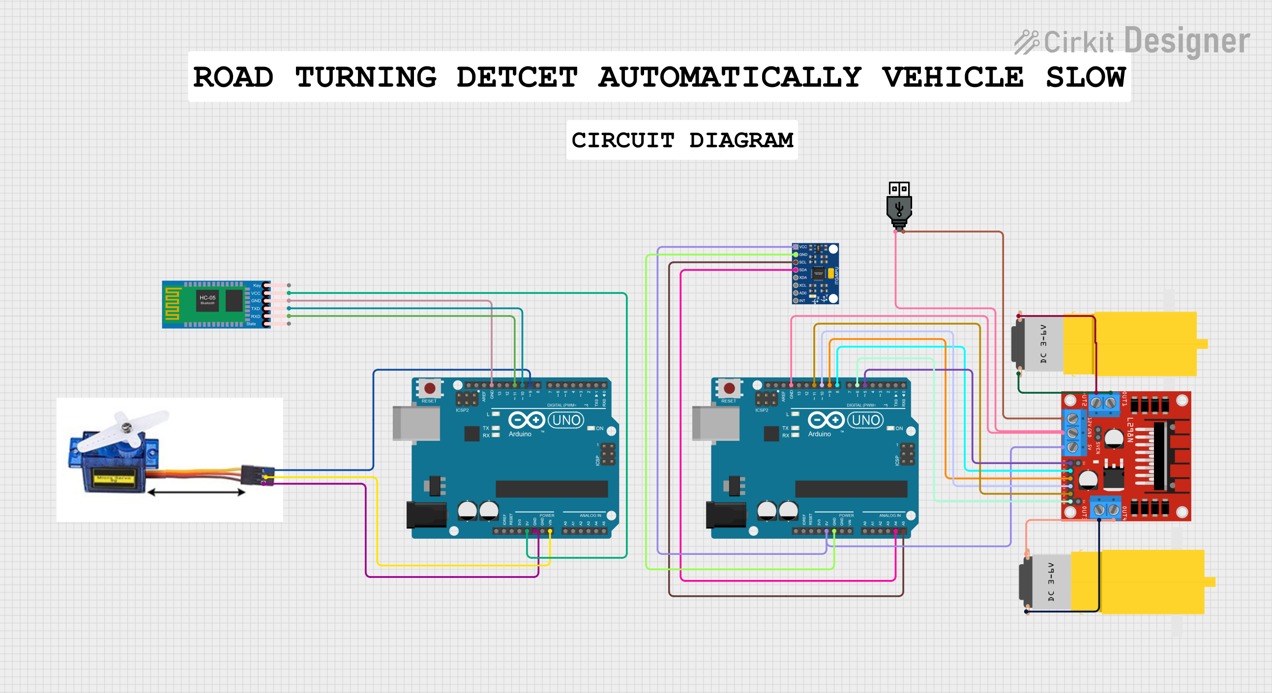
Explore Projects Built with Adafruit USB Boarduino
Common Applications and Use Cases
- Prototyping electronic circuits
- Educational projects in schools and workshops
- DIY home automation systems
- Robotics and control systems
- Wearable electronics
Technical Specifications
Key Technical Details
- Microcontroller: ATmega328
- Operating Voltage: 5V
- Input Voltage (recommended): 7-12V
- Input Voltage (limits): 6-20V
- Digital I/O Pins: 14 (of which 6 provide PWM output)
- Analog Input Pins: 6
- DC Current per I/O Pin: 40 mA
- DC Current for 3.3V Pin: 50 mA
- Flash Memory: 32 KB (ATmega328) of which 0.5 KB used by bootloader
- SRAM: 2 KB (ATmega328)
- EEPROM: 1 KB (ATmega328)
- Clock Speed: 16 MHz
- USB Connection: via FTDI
Pin Configuration and Descriptions
| Pin Number | Function | Description |
|---|---|---|
| 1 | RESET | Used to reset the microcontroller |
| 2-13 | Digital I/O | Digital input/output pins, PWM on 3, 5, 6, 9, 10, 11 |
| 14-19 | Analog Input | Analog input pins A0-A5 |
| 20 | AREF | Analog reference voltage for the ADC |
| 21 | GND | Ground |
| 22 | AVCC | Supply voltage for the ADC |
| 23 | 5V | Regulated 5V supply generated by the onboard regulator |
| 24 | 3.3V | Regulated 3.3V supply |
| 25 | VIN | Input voltage to the Boarduino |
Usage Instructions
How to Use the Component in a Circuit
Powering the Boarduino:
- Connect a 7-12V power supply to the VIN and GND pins, or plug in the USB cable to power the board from your computer.
Programming the Boarduino:
- Install the Arduino IDE on your computer.
- Connect the Boarduino to your computer using a USB cable.
- Select "Arduino UNO" in the Tools > Board menu.
- Write your sketch and upload it to the Boarduino using the IDE.
Using Digital I/O Pins:
- Configure the pins as INPUT or OUTPUT using the
pinMode()function. - Read digital inputs using the
digitalRead()function. - Set digital outputs using the
digitalWrite()function.
- Configure the pins as INPUT or OUTPUT using the
Using Analog Input Pins:
- Read analog inputs using the
analogRead()function.
- Read analog inputs using the
Using PWM Outputs:
- Generate PWM signals on pins 3, 5, 6, 9, 10, and 11 using the
analogWrite()function.
- Generate PWM signals on pins 3, 5, 6, 9, 10, and 11 using the
Important Considerations and Best Practices
- Always disconnect the Boarduino from power sources before making or altering connections.
- Ensure that the power supply voltage does not exceed the recommended limits to prevent damage.
- Use current-limiting resistors with LEDs and other sensitive components.
- Avoid drawing more than 40 mA from any I/O pin.
Example Code for Arduino UNO
// Blink an LED connected to pin 13

void setup() {
  pinMode(13, OUTPUT); // Set pin 13 as an output
}

void loop() {
  digitalWrite(13, HIGH); // Turn the LED on
  delay(1000);            // Wait for a second
  digitalWrite(13, LOW);  // Turn the LED off
  delay(1000);            // Wait for a second
}
Troubleshooting and FAQs
Common Issues
Boarduino not recognized by computer:
- Ensure the USB cable is properly connected and the computer's USB port is functioning.
- Check that the correct drivers for the FTDI USB interface are installed.
Sketch not uploading:
- Verify that the correct board and port are selected in the Arduino IDE.
- Press the reset button on the Boarduino just before uploading the sketch.
Unexpected behavior in circuits:
- Double-check wiring and connections on the breadboard.
- Ensure that power supply levels are within the specified limits.
Solutions and Tips for Troubleshooting
- If the Boarduino is not functioning as expected, try uploading a simple sketch like the Blink example to test basic functionality.
- Consult the Arduino forums and Adafruit support for assistance with specific issues.
- Always read the datasheet and reference materials provided by Adafruit for in-depth technical information.
FAQs
Q: Can I use the Boarduino with a 3.3V system? A: The Boarduino operates at 5V, but it has a 3.3V output pin that can be used to interface with 3.3V components. Be cautious with logic level conversions.
Q: How do I connect sensors to the Boarduino?
A: Sensors can be connected to the analog or digital I/O pins depending on their output type. Use the analogRead() or digitalRead() functions to read sensor data.
Q: Is the Boarduino compatible with all Arduino shields? A: The Boarduino is breadboard-friendly and may not be directly compatible with all Arduino shields designed for the standard Arduino form factor. However, you can wire compatible shields to the Boarduino using jumper wires.