How to Use Arduino Uno R3: Examples, Pinouts, and Specs
Arduino Uno R3 Documentation
1. Introduction
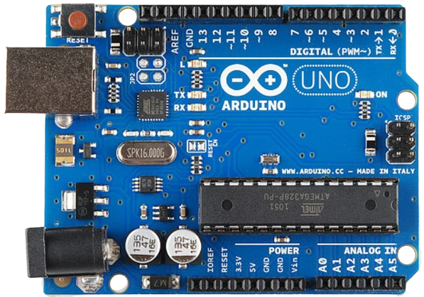
The Arduino Uno R3 is a microcontroller board based on the ATmega328P. It is designed for ease of use and flexibility, making it an ideal choice for both beginners and experienced developers. The board features 14 digital input/output pins, 6 analog inputs, a USB connection for programming, and a power jack.
Common applications of the Arduino Uno R3 include:
- Prototyping electronic circuits
- Building interactive projects such as robots and sensors
- Educational purposes in electronics and programming
- Home automation systems
- Art installations and interactive displays
2. Technical Specifications
Key Technical Details
| Specification | Details |
|---|---|
| Microcontroller | ATmega328P |
| Operating Voltage | 5V |
| Input Voltage (recommended) | 7-12V |
| Digital I/O Pins | 14 |
| PWM Digital I/O Pins | 6 |
| Analog Input Pins | 6 |
| Flash Memory | 32 KB (0.5 KB used by bootloader) |
| SRAM | 2 KB |
| EEPROM | 1 KB |
| Clock Speed | 16 MHz |
| USB Connection | Type B |
Pin Configuration and Descriptions
| Pin Number | Pin Name | Description |
|---|---|---|
| 1 | GND | Ground pin |
| 2 | 5V | 5V power output |
| 3 | Vin | Input voltage (7-12V) |
| 4 | Digital 0 (RX) | Receive pin for serial communication |
| 5 | Digital 1 (TX) | Transmit pin for serial communication |
| 6 | Digital 2 | Digital I/O pin |
| 7 | Digital 3 | Digital I/O pin (PWM) |
| 8 | Digital 4 | Digital I/O pin |
| 9 | Digital 5 | Digital I/O pin (PWM) |
| 10 | Digital 6 | Digital I/O pin (PWM) |
| 11 | Digital 7 | Digital I/O pin |
| 12 | Digital 8 | Digital I/O pin |
| 13 | Digital 9 | Digital I/O pin (LED on board) |
| 14 | Analog 0 | Analog input pin |
| 15 | Analog 1 | Analog input pin |
| 16 | Analog 2 | Analog input pin |
| 17 | Analog 3 | Analog input pin |
| 18 | Analog 4 | Analog input pin |
| 19 | Analog 5 | Analog input pin |
3. Usage Instructions
How to Use the Arduino Uno R3 in a Circuit
Powering the Board:
- Connect the board to a power source using the power jack or USB connection.
- Ensure the input voltage is within the recommended range (7-12V).
Connecting Components:
- Use jumper wires to connect sensors, LEDs, or other components to the digital or analog pins.
- Ensure correct polarity when connecting components like LEDs.
Programming the Board:
- Install the Arduino IDE on your computer.
- Connect the Arduino Uno R3 to your computer using a USB cable.
- Select the correct board and port in the Arduino IDE.
- Write your code and upload it to the board.
Important Considerations and Best Practices
- Always check the voltage ratings of components before connecting them to the board.
- Use resistors with LEDs to prevent damage from excessive current.
- Keep the board away from moisture and extreme temperatures.
- Regularly update the Arduino IDE for the latest features and bug fixes.
4. Troubleshooting and FAQs
Common Issues Users Might Face
Board Not Recognized by Computer:
- Ensure the USB cable is functioning and properly connected.
- Check if the correct port is selected in the Arduino IDE.
Code Upload Fails:
- Verify that the correct board type is selected in the IDE.
- Reset the board by pressing the reset button before uploading.
LED Not Lighting Up:
- Check the polarity of the LED and ensure it is connected to the correct pin.
- Verify that the code is correctly written to control the LED.
Solutions and Tips for Troubleshooting
- If the board is not recognized, try using a different USB port or cable.
- For code upload issues, try restarting the Arduino IDE and reconnecting the board.
- Use a multimeter to check connections and voltages if components are not functioning as expected.
Example Code for Arduino Uno R3
Here is a simple example code to blink an LED connected to digital pin 13:
// Blink an LED connected to digital pin 13
void setup() {
  // Set pin 13 as an output
  pinMode(13, OUTPUT);
}

void loop() {
  // Turn the LED on
  digitalWrite(13, HIGH);
  // Wait for 1 second
  delay(1000);
  // Turn the LED off
  digitalWrite(13, LOW);
  // Wait for 1 second
  delay(1000);
}
This code will make the LED blink on and off every second. Make sure to upload the code to your Arduino Uno R3 to see the effect.
By following this documentation, users can effectively utilize the Arduino Uno R3 for a variety of projects and applications. Happy tinkering!
Explore Projects Built with Arduino Uno R3
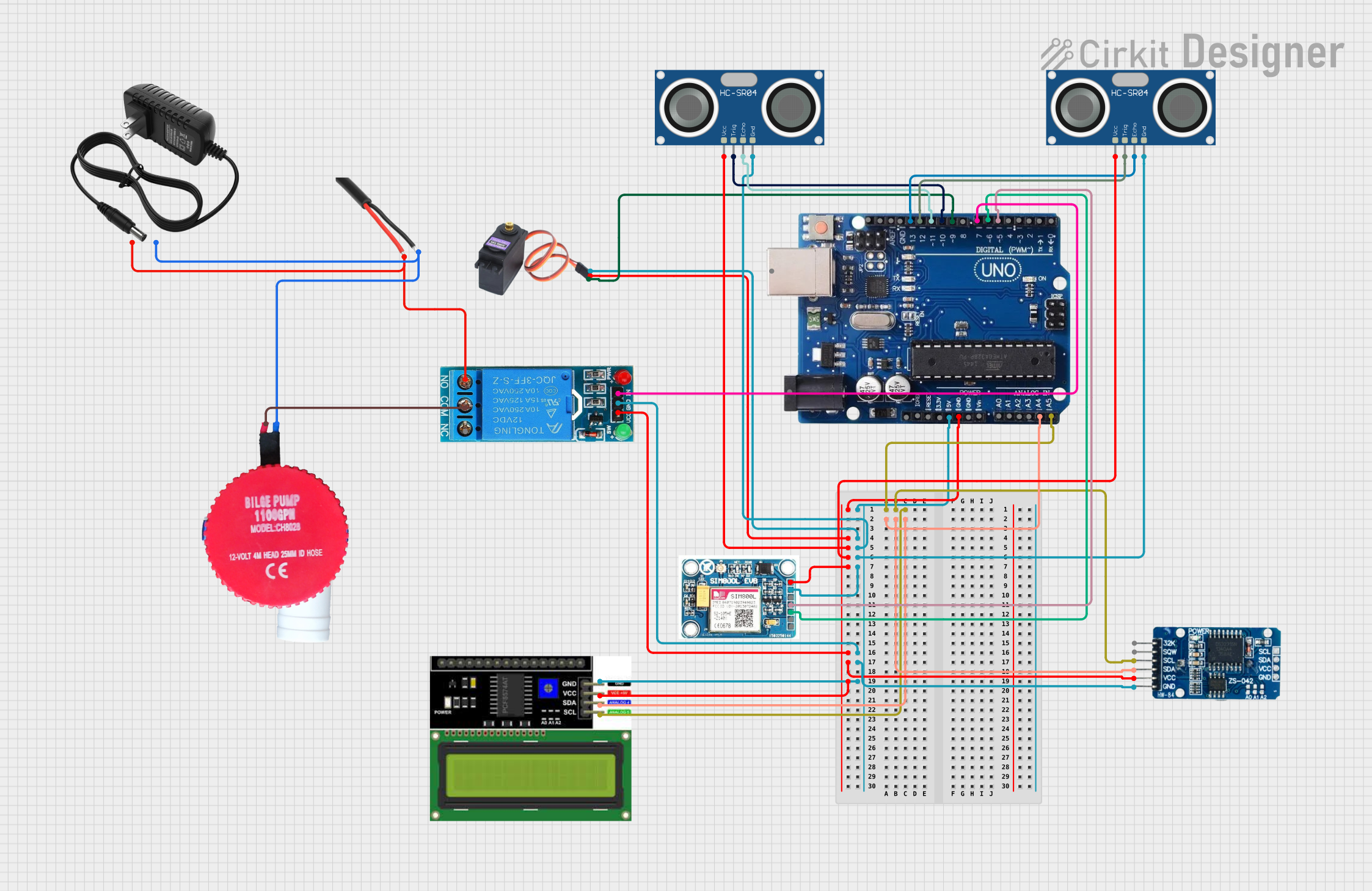
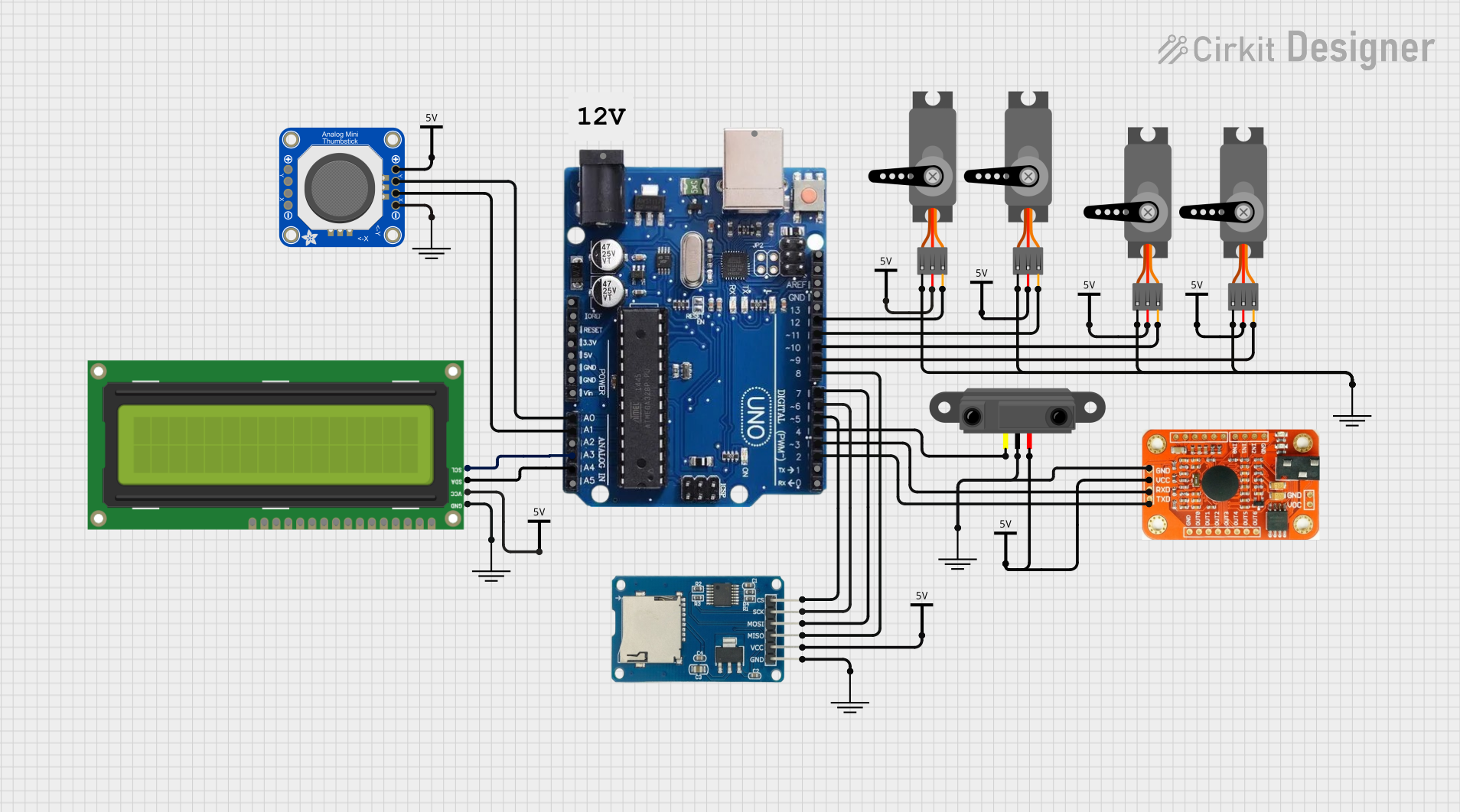
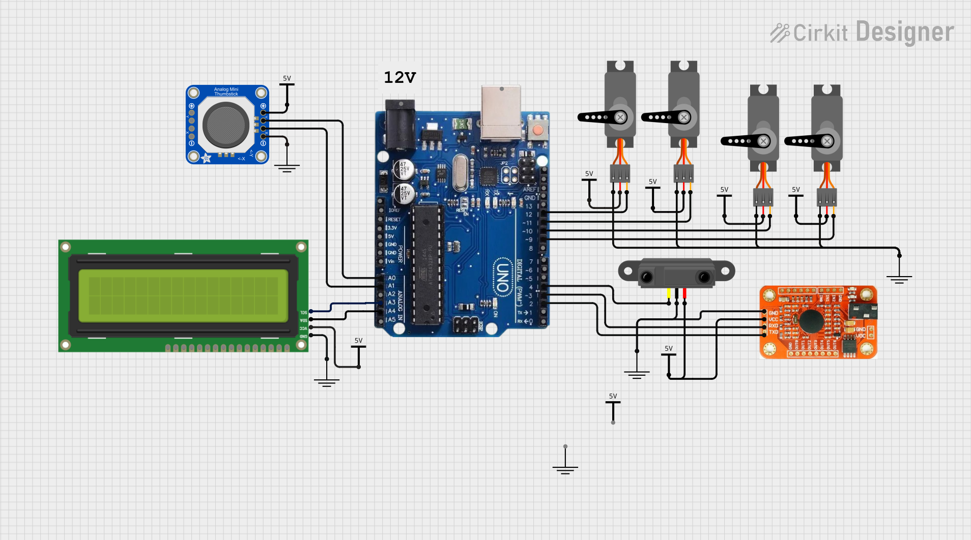
Explore Projects Built with Arduino Uno R3