How to Use Arduino 33 IOT: Examples, Pinouts, and Specs
Introduction
The Arduino 33 IoT is a powerful microcontroller board based on the ESP32, designed specifically for Internet of Things (IoT) applications. It features built-in Wi-Fi and Bluetooth connectivity, making it ideal for projects that require wireless communication. The board is compact, versatile, and compatible with the Arduino IDE, making it accessible for both beginners and experienced developers.
Explore Projects Built with Arduino 33 IOT

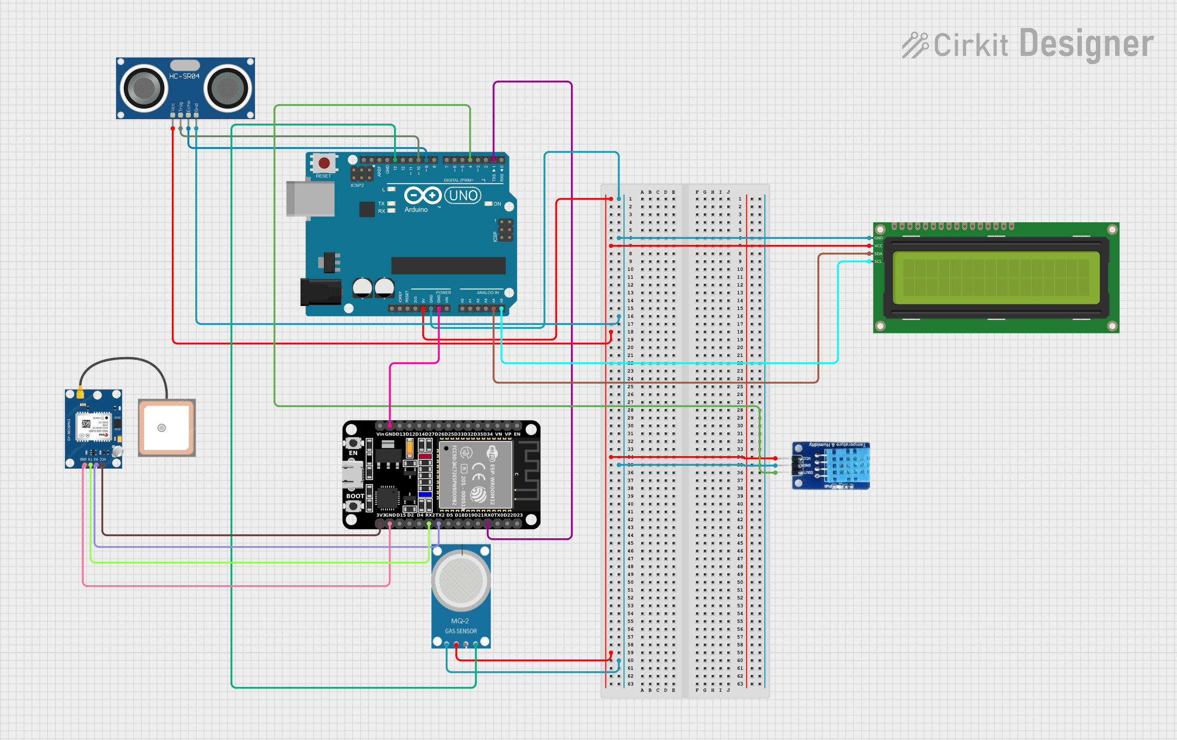
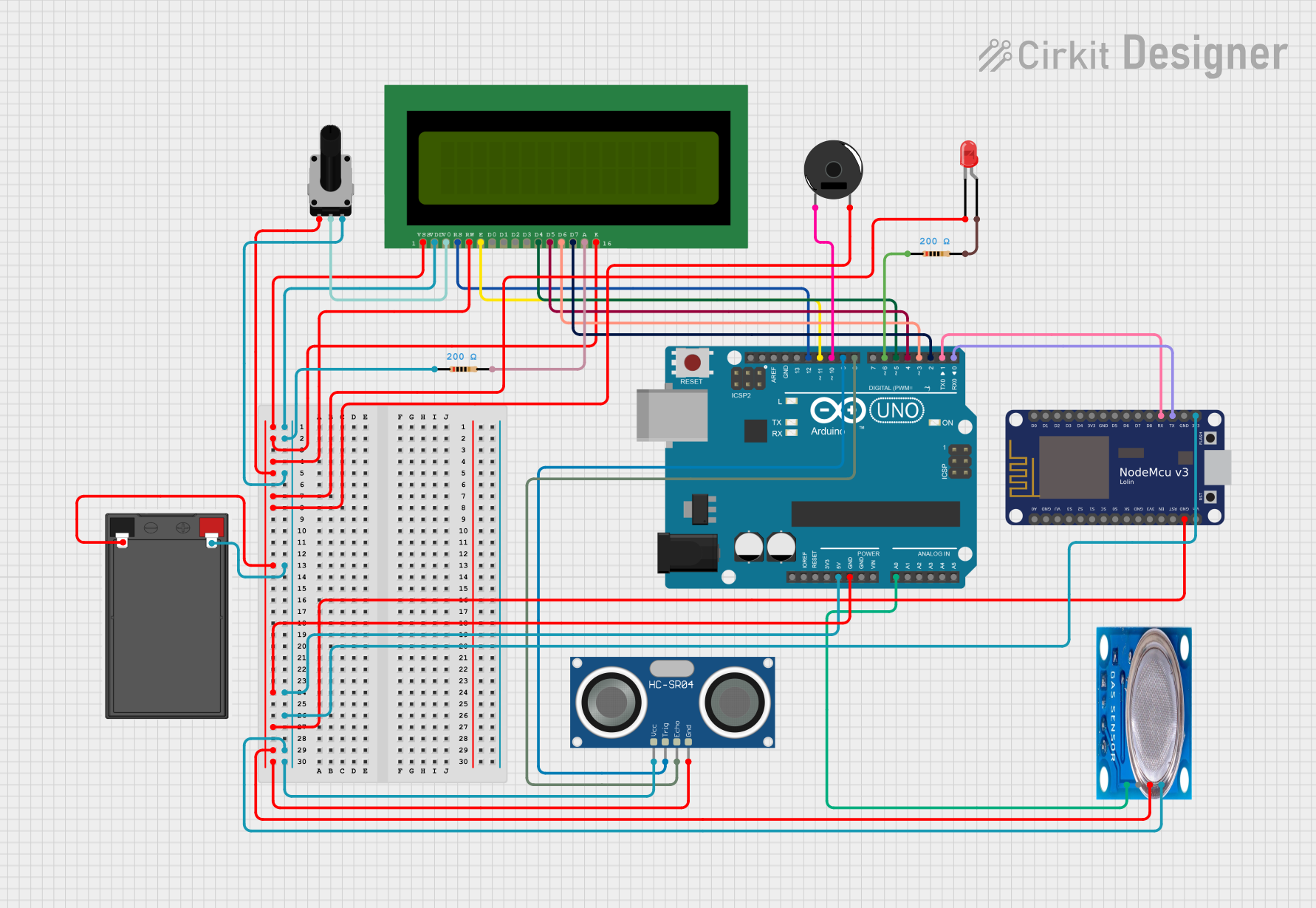
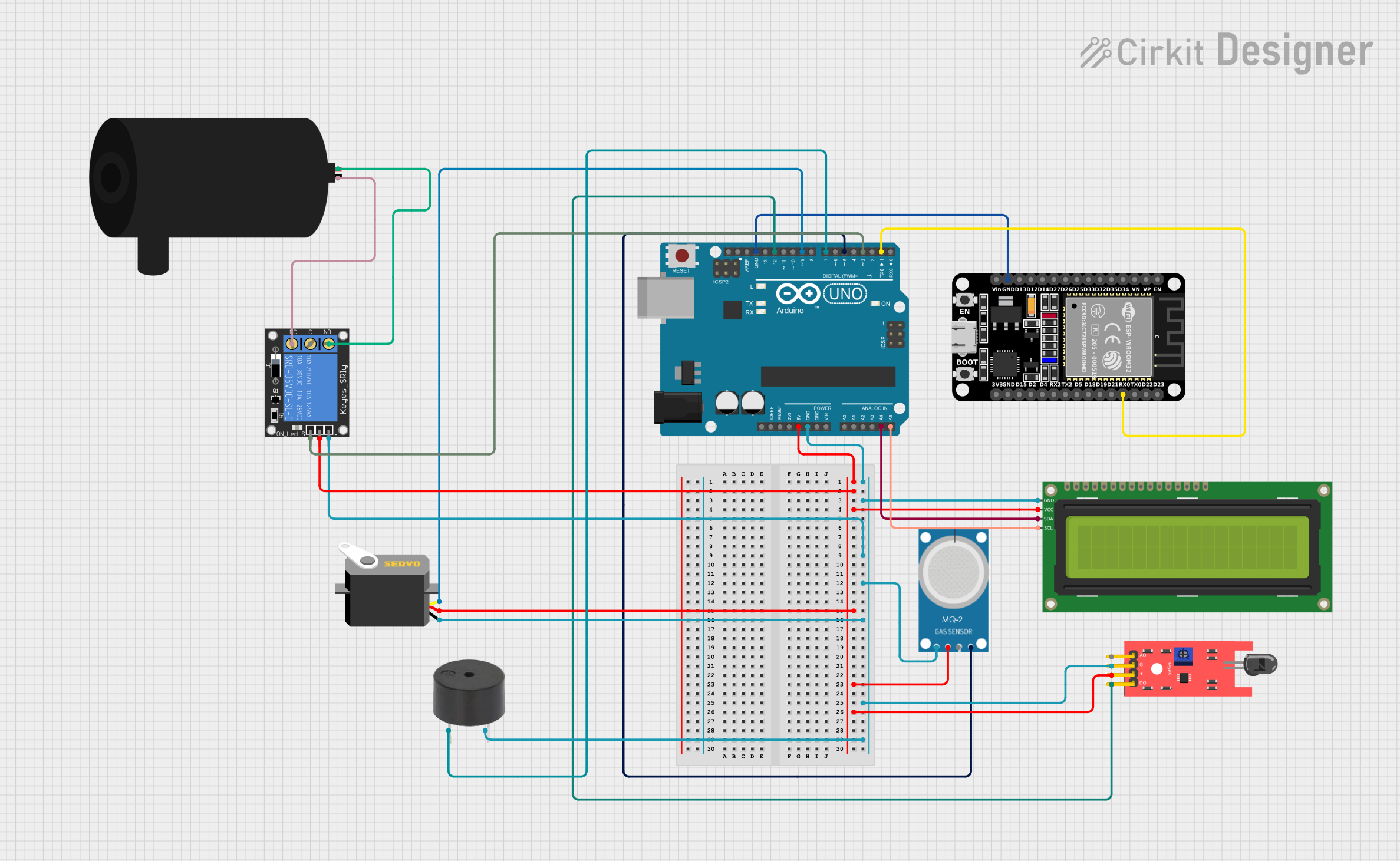
Explore Projects Built with Arduino 33 IOT
Common Applications and Use Cases
- Smart home automation systems
- Remote monitoring and control of devices
- IoT-enabled sensors and actuators
- Wearable technology
- Data logging and cloud integration
- Prototyping wireless communication systems
Technical Specifications
Key Technical Details
| Specification | Value |
|---|---|
| Microcontroller | ESP32 |
| Operating Voltage | 3.3V |
| Input Voltage (VIN) | 5V |
| Digital I/O Pins | 14 |
| PWM Pins | 11 |
| Analog Input Pins | 6 (12-bit ADC resolution) |
| Flash Memory | 4MB |
| SRAM | 520KB |
| Connectivity | Wi-Fi 802.11 b/g/n, Bluetooth 4.2 (BLE) |
| Clock Speed | 240 MHz |
| Dimensions | 68.6mm x 25.4mm |
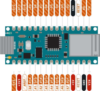
Pin Configuration and Descriptions
| Pin Name | Type | Description |
|---|---|---|
| VIN | Power Input | External power supply input (5V). |
| 3.3V | Power Output | Regulated 3.3V output. |
| GND | Ground | Ground connection. |
| A0-A5 | Analog Input | Analog input pins (0-3.3V, 12-bit ADC). |
| D0-D13 | Digital I/O | Digital input/output pins. |
| TX | UART TX | Transmit pin for serial communication. |
| RX | UART RX | Receive pin for serial communication. |
| SDA | I2C Data | Data line for I2C communication. |
| SCL | I2C Clock | Clock line for I2C communication. |
| MOSI | SPI Data Out | Master Out Slave In for SPI communication. |
| MISO | SPI Data In | Master In Slave Out for SPI communication. |
| SCK | SPI Clock | Clock line for SPI communication. |
| RST | Reset | Resets the microcontroller. |
Usage Instructions
How to Use the Arduino 33 IoT in a Circuit
Powering the Board:
- Connect the board to your computer via a USB cable for programming and power.
- Alternatively, use the VIN pin to supply 5V from an external power source.
Programming the Board:
- Install the Arduino IDE and add the ESP32 board package via the Board Manager.
- Select "Arduino 33 IoT" from the Tools > Board menu.
- Write your code and upload it to the board using the USB connection.
Connecting Sensors and Actuators:
- Use the digital and analog pins to interface with sensors and actuators.
- Ensure that the voltage levels of connected components are compatible with the 3.3V logic of the board.
Using Wi-Fi and Bluetooth:
- Use the built-in libraries (
WiFi.handBluetoothSerial.h) to enable wireless communication. - Configure the network credentials and communication protocols in your code.
- Use the built-in libraries (
Important Considerations and Best Practices
- Avoid supplying more than 3.3V to the analog or digital pins to prevent damage.
- Use level shifters if interfacing with 5V logic devices.
- Ensure proper grounding between the Arduino 33 IoT and connected components.
- Use decoupling capacitors for noise-sensitive applications.
- When using Wi-Fi or Bluetooth, ensure a stable power supply to avoid connectivity issues.
Example Code: Connecting to Wi-Fi
#include <WiFi.h> // Include the Wi-Fi library

const char* ssid = "Your_SSID";       // Replace with your Wi-Fi network name
const char* password = "Your_Password"; // Replace with your Wi-Fi password

void setup() {
  Serial.begin(115200); // Initialize serial communication at 115200 baud
  Serial.println("Connecting to Wi-Fi...");

  WiFi.begin(ssid, password); // Start Wi-Fi connection

  while (WiFi.status() != WL_CONNECTED) {
    delay(1000); // Wait for connection
    Serial.println("Attempting to connect...");
  }

  Serial.println("Connected to Wi-Fi!");
  Serial.print("IP Address: ");
  Serial.println(WiFi.localIP()); // Print the assigned IP address
}

void loop() {
  // Add your main code here
}
Troubleshooting and FAQs
Common Issues and Solutions
The board is not detected by the Arduino IDE:
- Ensure the correct USB cable is used (data + power, not power-only).
- Install the necessary drivers for the ESP32.
- Check that the correct COM port is selected in the Tools menu.
Wi-Fi connection fails:
- Double-check the SSID and password in your code.
- Ensure the Wi-Fi network is operational and within range.
- Restart the board and router if necessary.
Bluetooth communication is unstable:
- Verify that the paired device supports Bluetooth 4.2 or BLE.
- Minimize interference from other wireless devices.
The board overheats:
- Avoid overloading the GPIO pins with excessive current.
- Use a heat sink or active cooling if operating in high-temperature environments.
FAQs
Q: Can I use the Arduino 33 IoT with 5V sensors?
A: Yes, but you will need a level shifter to step down the voltage to 3.3V.
Q: Does the board support OTA (Over-The-Air) updates?
A: Yes, the ESP32 supports OTA updates. You can use the Arduino IDE or other tools to implement this feature.
Q: Can I power the board with a battery?
A: Yes, you can use a 3.7V LiPo battery connected to the VIN pin, but ensure proper voltage regulation.
Q: Is the Arduino 33 IoT compatible with Arduino shields?
A: The board is not directly compatible with standard Arduino shields due to its pin layout and 3.3V logic. However, you can use jumper wires to connect shields manually.