Cirkit Designer Logo
Cirkit Designer
Your all-in-one circuit design IDE
Home / 
Component Documentation

How to Use V4 R828D RTL2832U 1PPM TCXO SMA Software Defined Radio: Examples, Pinouts, and Specs

Image of V4 R828D RTL2832U 1PPM TCXO SMA Software Defined Radio
Cirkit Designer LogoDesign with V4 R828D RTL2832U 1PPM TCXO SMA Software Defined Radio in Cirkit Designer

Introduction

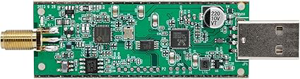
The V4 R828D RTL2832U 1PPM TCXO SMA Software Defined Radio (SDR), manufactured by RTL-SDR Blog (Part ID: rtlsdr_v4_dongle_only), is a versatile and affordable SDR device. It is based on the RTL2832U chipset and features a 1PPM temperature-compensated crystal oscillator (TCXO) for enhanced frequency stability. The device is equipped with an SMA connector for easy antenna interfacing and supports a wide range of frequencies, making it suitable for various radio communication applications.

Explore Projects Built with V4 R828D RTL2832U 1PPM TCXO SMA Software Defined Radio

Use Cirkit Designer to design, explore, and prototype these projects online. Some projects support real-time simulation. Click "Open Project" to start designing instantly!
Satellite-Based Timing and Navigation System with SDR and Atomic Clock Synchronization
Image of GPS 시스템 측정 구성도_Confirm: A project utilizing V4 R828D RTL2832U 1PPM TCXO SMA Software Defined Radio in a practical application
This circuit appears to be a complex system involving power supply management, GPS and timing synchronization, and data communication. It includes a SI-TEX G1 Satellite Compass for GPS data, an XHTF1021 Atomic Rubidium Clock for precise timing, and Ettus USRP B200 units for software-defined radio communication. Power is supplied through various SMPS units and distributed via terminal blocks and DC jacks. Data communication is facilitated by Beelink MINI S12 N95 computers, RS232 splitters, and a 1000BASE-T Media Converter for network connectivity. RF Directional Couplers are used to interface antennas with the USRP units, and the entire system is likely contained within cases for protection and organization.
Cirkit Designer LogoOpen Project in Cirkit Designer
Satellite Compass and Network-Integrated GPS Data Processing System
Image of GPS 시스템 측정 구성도_241016: A project utilizing V4 R828D RTL2832U 1PPM TCXO SMA Software Defined Radio in a practical application
This circuit comprises a satellite compass, a mini PC, two GPS antennas, power supplies, a network switch, media converters, and an atomic rubidium clock. The satellite compass is powered by a triple output DC power supply and interfaces with an RS232 splitter for 1PPS signals. The mini PCs are connected to the USRP B200 devices via USB for data and power, and to media converters via Ethernet, which in turn connect to a network switch using fiber optic links. The antennas are connected to the USRP B200s through RF directional couplers, and the atomic clock provides a 1PPS input to the RS232 splitter.
Cirkit Designer LogoOpen Project in Cirkit Designer
Cellular-Enabled IoT Device with Real-Time Clock and Power Management
Image of LRCM PHASE 2 BASIC: A project utilizing V4 R828D RTL2832U 1PPM TCXO SMA Software Defined Radio in a practical application
This circuit features a LilyGo-SIM7000G module for cellular communication and GPS functionality, interfaced with an RTC DS3231 for real-time clock capabilities. It includes voltage sensing through two voltage sensor modules, and uses an 8-channel opto-coupler for isolating different parts of the circuit. Power management is handled by a buck converter connected to a DC power source and batteries, with a fuse for protection and a rocker switch for on/off control. Additionally, there's an LED for indication purposes.
Cirkit Designer LogoOpen Project in Cirkit Designer
Laptop-Connected Adalm Pluto SDR with Dual Antennas
Image of Zidan Project: A project utilizing V4 R828D RTL2832U 1PPM TCXO SMA Software Defined Radio in a practical application
This circuit connects an Adalm Pluto Software Defined Radio (SDR) to a laptop via a Type-B to USB cable, allowing the laptop to control the SDR and process signals. Additionally, two antennas are connected to the Adalm Pluto SDR, which are likely used for transmitting and receiving radio signals as part of the SDR's functionality.
Cirkit Designer LogoOpen Project in Cirkit Designer

Explore Projects Built with V4 R828D RTL2832U 1PPM TCXO SMA Software Defined Radio

Use Cirkit Designer to design, explore, and prototype these projects online. Some projects support real-time simulation. Click "Open Project" to start designing instantly!
Image of GPS 시스템 측정 구성도_Confirm: A project utilizing V4 R828D RTL2832U 1PPM TCXO SMA Software Defined Radio in a practical application
Satellite-Based Timing and Navigation System with SDR and Atomic Clock Synchronization
This circuit appears to be a complex system involving power supply management, GPS and timing synchronization, and data communication. It includes a SI-TEX G1 Satellite Compass for GPS data, an XHTF1021 Atomic Rubidium Clock for precise timing, and Ettus USRP B200 units for software-defined radio communication. Power is supplied through various SMPS units and distributed via terminal blocks and DC jacks. Data communication is facilitated by Beelink MINI S12 N95 computers, RS232 splitters, and a 1000BASE-T Media Converter for network connectivity. RF Directional Couplers are used to interface antennas with the USRP units, and the entire system is likely contained within cases for protection and organization.
Cirkit Designer LogoOpen Project in Cirkit Designer
Image of GPS 시스템 측정 구성도_241016: A project utilizing V4 R828D RTL2832U 1PPM TCXO SMA Software Defined Radio in a practical application
Satellite Compass and Network-Integrated GPS Data Processing System
This circuit comprises a satellite compass, a mini PC, two GPS antennas, power supplies, a network switch, media converters, and an atomic rubidium clock. The satellite compass is powered by a triple output DC power supply and interfaces with an RS232 splitter for 1PPS signals. The mini PCs are connected to the USRP B200 devices via USB for data and power, and to media converters via Ethernet, which in turn connect to a network switch using fiber optic links. The antennas are connected to the USRP B200s through RF directional couplers, and the atomic clock provides a 1PPS input to the RS232 splitter.
Cirkit Designer LogoOpen Project in Cirkit Designer
Image of LRCM PHASE 2 BASIC: A project utilizing V4 R828D RTL2832U 1PPM TCXO SMA Software Defined Radio in a practical application
Cellular-Enabled IoT Device with Real-Time Clock and Power Management
This circuit features a LilyGo-SIM7000G module for cellular communication and GPS functionality, interfaced with an RTC DS3231 for real-time clock capabilities. It includes voltage sensing through two voltage sensor modules, and uses an 8-channel opto-coupler for isolating different parts of the circuit. Power management is handled by a buck converter connected to a DC power source and batteries, with a fuse for protection and a rocker switch for on/off control. Additionally, there's an LED for indication purposes.
Cirkit Designer LogoOpen Project in Cirkit Designer
Image of Zidan Project: A project utilizing V4 R828D RTL2832U 1PPM TCXO SMA Software Defined Radio in a practical application
Laptop-Connected Adalm Pluto SDR with Dual Antennas
This circuit connects an Adalm Pluto Software Defined Radio (SDR) to a laptop via a Type-B to USB cable, allowing the laptop to control the SDR and process signals. Additionally, two antennas are connected to the Adalm Pluto SDR, which are likely used for transmitting and receiving radio signals as part of the SDR's functionality.
Cirkit Designer LogoOpen Project in Cirkit Designer

Common Applications and Use Cases

  • Amateur Radio: Receive and decode amateur radio signals.
  • Weather Satellite Reception: Decode NOAA and other weather satellite transmissions.
  • Air Traffic Monitoring: Track ADS-B signals from aircraft.
  • Radio Astronomy: Capture and analyze weak radio signals from space.
  • General Radio Scanning: Listen to FM radio, police, fire, and other public service bands.
  • IoT and Wireless Protocol Analysis: Analyze signals from IoT devices and wireless protocols like Zigbee.

Technical Specifications

The following table outlines the key technical details of the V4 R828D RTL2832U SDR:

Parameter Specification
Chipset RTL2832U + R828D
Frequency Range 1 kHz to 1.766 GHz (with gaps)
TCXO Stability 1PPM (Temperature-Compensated Crystal Oscillator)
Sampling Rate Up to 3.2 MSPS (Million Samples Per Second)
Connector Type SMA Female
Antenna Compatibility Compatible with SMA antennas (external antennas required)
Power Supply USB-powered (5V, via USB Type-A connector)
Operating System Support Windows, Linux, macOS, Android (via compatible SDR software)
Software Compatibility SDR# (SDRSharp), GQRX, CubicSDR, GNU Radio, and other SDR software
Dimensions 70 mm x 25 mm x 10 mm

Pin Configuration and Descriptions

The V4 R828D SDR is a USB dongle and does not have traditional pins. However, the following table describes its key interfaces:

Interface Description
USB Type-A Connects to the host device (PC, Raspberry Pi, etc.) for power and data transfer.
SMA Connector Connects to an external antenna for signal reception.
LED Indicator Indicates power and operational status.

Usage Instructions

How to Use the V4 R828D RTL2832U SDR in a Circuit

  1. Connect the SDR to a Host Device:

    • Plug the USB Type-A connector into a compatible host device (e.g., PC, Raspberry Pi).
    • Ensure the host device has the necessary SDR software installed (e.g., SDR#, GQRX).
  2. Attach an Antenna:

    • Connect an SMA-compatible antenna to the SMA connector on the SDR.
    • Use an appropriate antenna for the frequency range you intend to monitor.
  3. Install Drivers:

    • On Windows, use the Zadig tool to replace the default USB driver with the WinUSB driver.
    • On Linux/macOS, most distributions include native support for RTL-SDR devices.
  4. Launch SDR Software:

    • Open your preferred SDR software (e.g., SDR# or GQRX).
    • Configure the software to use the RTL-SDR as the input device.
    • Set the desired frequency range and sampling rate.
  5. Start Receiving Signals:

    • Tune to the desired frequency and adjust gain settings for optimal reception.
    • Use software features like demodulation, filtering, and spectrum analysis to process signals.

Important Considerations and Best Practices

  • Antenna Selection: Use an antenna designed for the frequency range you want to monitor. For example, a discone antenna is suitable for wideband reception.
  • Avoid Overloading: Strong nearby signals can overload the SDR. Use an attenuator or bandpass filter if necessary.
  • Cooling: The SDR may become warm during operation. Ensure adequate ventilation to prevent overheating.
  • Frequency Calibration: The 1PPM TCXO provides excellent stability, but you may still need to perform minor frequency corrections in software.

Example: Using the SDR with an Arduino UNO

While the V4 R828D SDR is primarily used with PCs or Raspberry Pi, it can interface with an Arduino UNO for specific applications, such as controlling the SDR or processing received data. Below is an example of Arduino code to control the SDR's frequency via USB:

#include <SoftwareSerial.h>

// Define RX and TX pins for software serial communication
SoftwareSerial SDRSerial(10, 11); // RX = pin 10, TX = pin 11

void setup() {
  // Initialize serial communication with the SDR
  SDRSerial.begin(9600); // Adjust baud rate as needed
  Serial.begin(9600);    // For debugging via the Arduino Serial Monitor

  // Send a command to set the SDR frequency (example: 100 MHz)
  SDRSerial.println("SETFREQ 100000000"); // Command to set frequency to 100 MHz
  Serial.println("Frequency set to 100 MHz");
}

void loop() {
  // Continuously read data from the SDR and print to Serial Monitor
  if (SDRSerial.available()) {
    String data = SDRSerial.readString();
    Serial.println("SDR Data: " + data);
  }
}

Note: This example assumes the SDR supports serial commands for frequency control. Check the SDR's documentation for supported commands.

Troubleshooting and FAQs

Common Issues and Solutions

  1. No Signal Reception:

    • Ensure the antenna is properly connected to the SMA port.
    • Verify that the correct frequency range is selected in the SDR software.
    • Check for driver installation issues (use Zadig on Windows).
  2. Poor Signal Quality:

    • Use a higher-quality antenna or relocate the antenna to a better position.
    • Add a low-noise amplifier (LNA) to boost weak signals.
    • Use bandpass filters to reduce interference from unwanted frequencies.
  3. Device Not Recognized:

    • Ensure the USB port is functional and provides sufficient power.
    • Reinstall the drivers using Zadig or update the SDR software.
  4. Overheating:

    • Operate the SDR in a well-ventilated area.
    • Consider using a USB extension cable to keep the SDR away from heat sources.

FAQs

Q: Can the V4 R828D SDR transmit signals?
A: No, this SDR is a receive-only device. It cannot transmit signals.

Q: What is the purpose of the 1PPM TCXO?
A: The 1PPM TCXO ensures high frequency stability, reducing drift over time and temperature changes.

Q: Can I use this SDR with a Raspberry Pi?
A: Yes, the SDR is compatible with Raspberry Pi. Install the rtl-sdr package and use software like GQRX or CubicSDR.

Q: What is the maximum frequency range of this SDR?
A: The SDR supports frequencies from 1 kHz to 1.766 GHz, with some gaps.

Q: Do I need an internet connection to use the SDR?
A: No, an internet connection is not required for basic SDR operation. However, some applications (e.g., downloading satellite data) may require internet access.