How to Use IRF510: Examples, Pinouts, and Specs
Introduction
The IRF510 is an N-channel MOSFET (Metal-Oxide-Semiconductor Field-Effect Transistor) designed for switching and amplifying electronic signals. It is widely used in power electronics due to its low on-resistance, high voltage, and current handling capabilities. The IRF510 is particularly suitable for applications such as motor control, power supplies, audio amplifiers, and RF circuits.
Explore Projects Built with IRF510


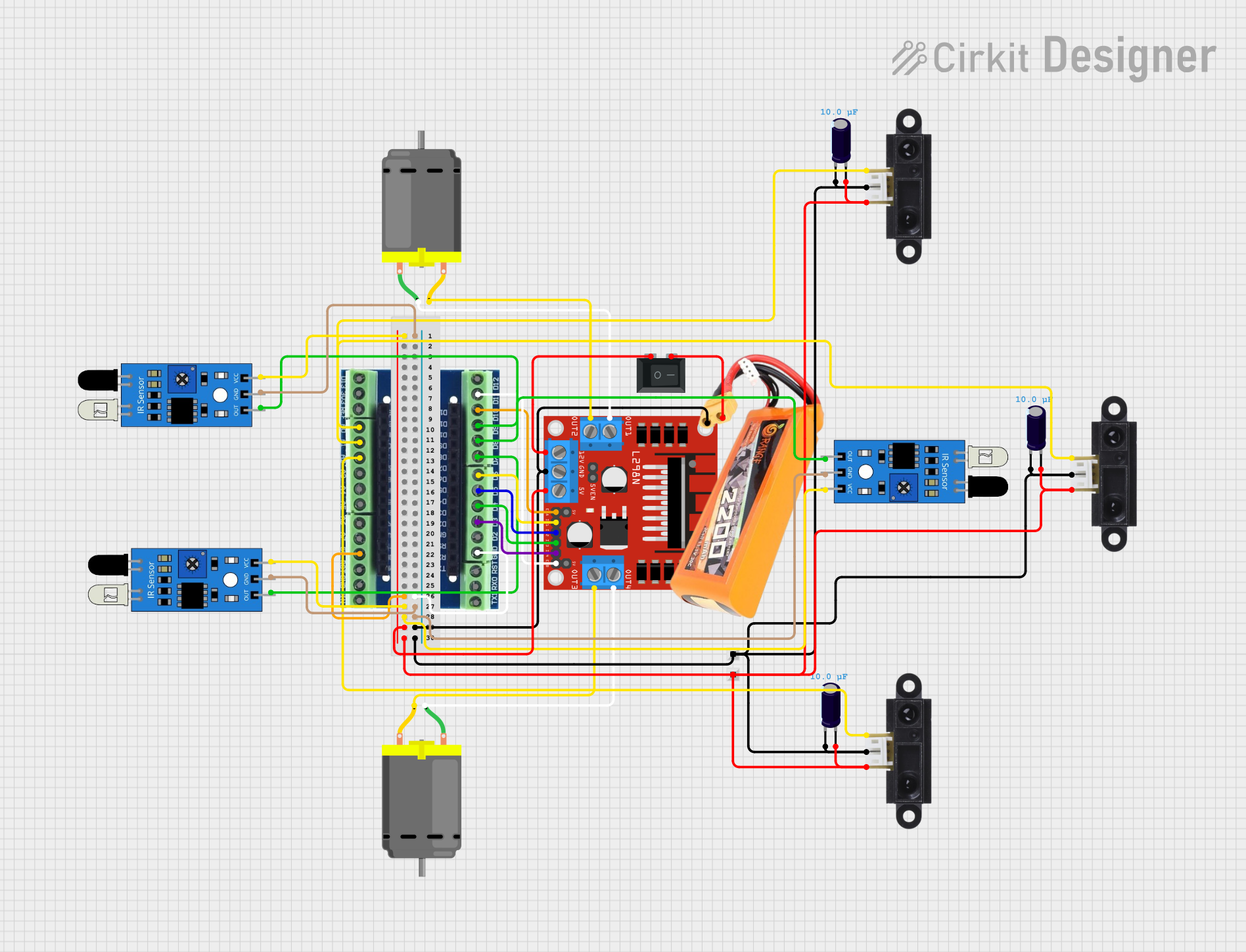
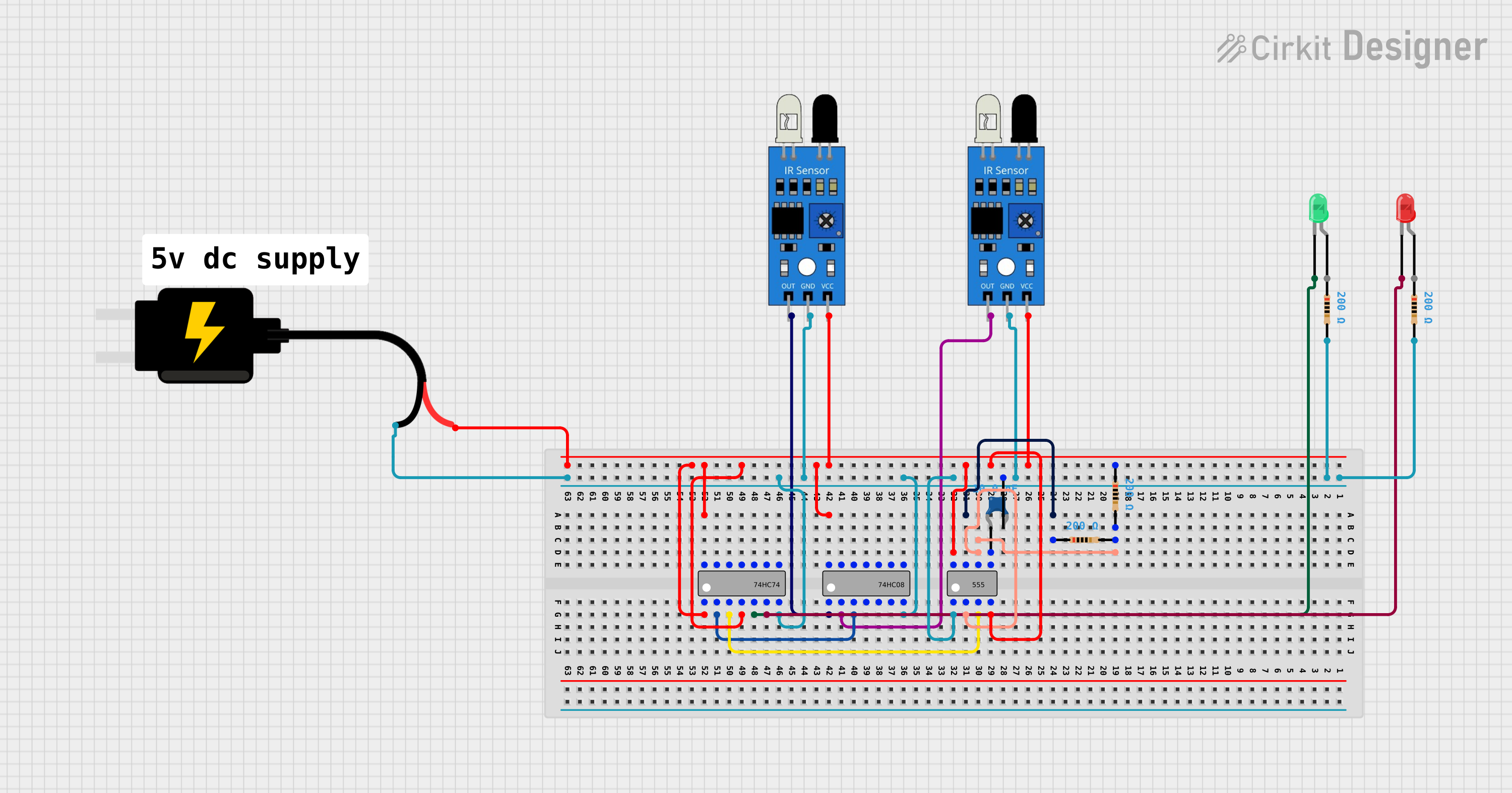
Explore Projects Built with IRF510
Common Applications:
- DC motor drivers
- Switching power supplies
- Audio amplifiers
- RF amplifiers
- General-purpose switching circuits
Technical Specifications
Below are the key technical details of the IRF510 MOSFET:
| Parameter | Value |
|---|---|
| Type | N-Channel MOSFET |
| Maximum Drain-Source Voltage (VDS) | 100V |
| Maximum Gate-Source Voltage (VGS) | ±20V |
| Continuous Drain Current (ID) | 5.6A (at 25°C) |
| Pulsed Drain Current (IDM) | 20A |
| Power Dissipation (PD) | 43W (at 25°C) |
| On-Resistance (RDS(on)) | 0.54Ω (at VGS = 10V) |
| Gate Threshold Voltage (VGS(th)) | 2.0V - 4.0V |
| Operating Temperature Range | -55°C to +175°C |
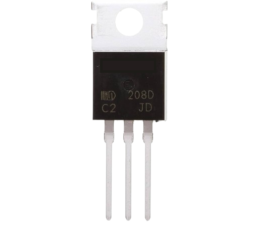
| Package Type | TO-220 |
Pin Configuration
The IRF510 comes in a TO-220 package with three pins. The pinout is as follows:
| Pin Number | Pin Name | Description |
|---|---|---|
| 1 | Gate (G) | Controls the MOSFET's switching state. |
| 2 | Drain (D) | Current flows from drain to source when |
| the MOSFET is on. | ||
| 3 | Source (S) | Connected to the ground or load. |
Usage Instructions
How to Use the IRF510 in a Circuit
- Gate Control: Apply a voltage to the Gate (Pin 1) to control the MOSFET. A voltage of at least 10V is recommended for full switching.
- Drain-Source Connection: Connect the load between the Drain (Pin 2) and the positive supply voltage. The Source (Pin 3) is typically connected to ground.
- Gate Resistor: Use a resistor (e.g., 220Ω) between the Gate and the control signal to limit current and prevent oscillations.
- Flyback Diode: For inductive loads (e.g., motors), add a flyback diode across the load to protect the MOSFET from voltage spikes.
Important Considerations
- Gate Drive Voltage: Ensure the Gate voltage (VGS) is sufficient to fully turn on the MOSFET. A voltage of 10V is ideal for minimizing on-resistance.
- Heat Dissipation: Use a heatsink if the MOSFET operates at high currents to prevent overheating.
- Load Type: For inductive loads, always include a flyback diode to protect the MOSFET.
- Switching Speed: The IRF510 is not optimized for high-speed switching applications. For such cases, consider using a MOSFET with lower gate capacitance.
Example: Using IRF510 with Arduino UNO
Below is an example of how to use the IRF510 to control a DC motor with an Arduino UNO:
// Define the pin connected to the MOSFET Gate
const int mosfetGatePin = 9;

void setup() {
  // Set the MOSFET Gate pin as an output
  pinMode(mosfetGatePin, OUTPUT);
}

void loop() {
  // Turn the motor on by setting the Gate HIGH
  digitalWrite(mosfetGatePin, HIGH);
  delay(1000); // Keep the motor on for 1 second

  // Turn the motor off by setting the Gate LOW
  digitalWrite(mosfetGatePin, LOW);
  delay(1000); // Keep the motor off for 1 second
}
Note: Ensure the Gate voltage is boosted to 10V using a Gate driver circuit if the Arduino's 5V logic level is insufficient to fully turn on the IRF510.
Troubleshooting and FAQs
Common Issues
MOSFET Not Turning On Fully:
- Cause: Insufficient Gate voltage (VGS).
- Solution: Use a Gate driver circuit to boost the control signal to 10V.
Overheating:
- Cause: High current through the MOSFET without proper heat dissipation.
- Solution: Attach a heatsink to the MOSFET and ensure proper ventilation.
MOSFET Fails to Switch:
- Cause: Missing Gate resistor or incorrect wiring.
- Solution: Add a resistor (e.g., 220Ω) between the Gate and the control signal. Double-check the wiring.
Voltage Spikes Damaging the MOSFET:
- Cause: Inductive load without a flyback diode.
- Solution: Add a flyback diode across the load to suppress voltage spikes.
FAQs
Q1: Can the IRF510 be used with a 3.3V microcontroller?
A1: No, the IRF510 requires a Gate voltage of at least 10V for full switching. Use a Gate driver circuit to interface with 3.3V logic.
Q2: What is the maximum current the IRF510 can handle?
A2: The IRF510 can handle up to 5.6A continuously at 25°C. For higher currents, ensure proper cooling with a heatsink.
Q3: Is the IRF510 suitable for high-frequency switching?
A3: The IRF510 is not optimized for high-frequency applications due to its relatively high Gate capacitance. Consider using a MOSFET designed for high-speed switching.
Q4: Can I use the IRF510 for audio amplification?
A4: Yes, the IRF510 can be used in audio amplifier circuits, particularly in Class A or Class AB configurations.