
How to Use WeMos D1 Mini Relay Shield V2: Examples, Pinouts, and Specs
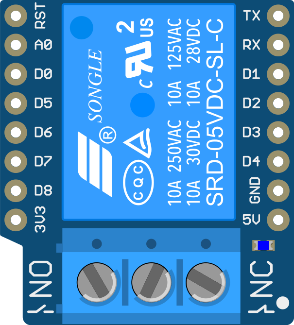
 Design with WeMos D1 Mini Relay Shield V2 in Cirkit Designer
Introduction
The WeMos D1 Mini Relay Shield V2 is a compact and versatile relay module designed specifically for the WeMos D1 Mini microcontroller. This shield allows users to control high-voltage devices (such as lights, fans, or appliances) using low-voltage signals from the D1 Mini. It is ideal for IoT applications, home automation projects, and other scenarios where electrical load switching is required.
Explore Projects Built with WeMos D1 Mini Relay Shield V2
 Open Project in Cirkit Designer
 Open Project in Cirkit Designer
 Open Project in Cirkit Designer
 Open Project in Cirkit Designer
Explore Projects Built with WeMos D1 Mini Relay Shield V2
Open Project in Cirkit DesignerOpen Project in Cirkit DesignerOpen Project in Cirkit DesignerOpen Project in Cirkit DesignerCommon Applications and Use Cases
- Home automation (e.g., controlling lights, fans, or appliances)
- IoT projects requiring high-voltage device control
- Industrial automation and control systems
- Smart energy management systems
- Prototyping and educational projects
Technical Specifications
The WeMos D1 Mini Relay Shield V2 is designed to work seamlessly with the D1 Mini and features the following specifications:
Key Technical Details
| Parameter | Specification |
|---|---|
| Operating Voltage | 5V DC (powered via D1 Mini) |
| Trigger Voltage | 3.3V (compatible with D1 Mini GPIO) |
| Relay Type | SPDT (Single Pole Double Throw) |
| Maximum Load Voltage | 250V AC / 30V DC |
| Maximum Load Current | 10A |
| Dimensions | 34.2mm x 25.6mm x 19.3mm |
| Weight | ~10g |
Pin Configuration and Descriptions
The relay shield connects directly to the WeMos D1 Mini via its pin headers. Below is the pin configuration:
| Pin Name | Description |
|---|---|
| VCC | 5V power supply input (provided by the D1 Mini) |
| GND | Ground connection |
| IN | Control signal input (connect to a GPIO pin on the D1 Mini) |
| NO | Normally Open terminal (connect to the load for default OFF state) |
| NC | Normally Closed terminal (connect to the load for default ON state) |
| COM | Common terminal (connect to the power source or load as required) |
Usage Instructions
How to Use the Component in a Circuit
Hardware Setup:
- Attach the WeMos D1 Mini Relay Shield V2 directly to the D1 Mini using the pin headers.
- Connect the high-voltage device (e.g., a light bulb) to the relay terminals:
- Connect one wire of the device to the
COMterminal. - Connect the other wire to either the
NO(Normally Open) orNC(Normally Closed) terminal, depending on the desired default state.
- Connect one wire of the device to the
- Ensure the D1 Mini is powered via USB or an external power source.
Software Setup:
- Use the GPIO pin connected to the relay's
INpin to control the relay. - A HIGH signal (3.3V) will activate the relay, while a LOW signal (0V) will deactivate it.
- Use the GPIO pin connected to the relay's
Example Circuit:
- Connect a 220V AC light bulb to the
COMandNOterminals. - Use GPIO D1 (pin 5) on the D1 Mini to control the relay.
- Connect a 220V AC light bulb to the
Important Considerations and Best Practices
- Safety First: Always ensure the high-voltage side of the relay is properly insulated to avoid electric shock or short circuits.
- Load Ratings: Do not exceed the maximum voltage (250V AC / 30V DC) or current (10A) ratings of the relay.
- Power Supply: Ensure the D1 Mini is powered with a stable 5V source to avoid relay malfunction.
- Inductive Loads: When switching inductive loads (e.g., motors), use a flyback diode across the load to protect the relay from voltage spikes.
Example Code for Arduino UNO
Below is an example code snippet to control the relay shield using the D1 Mini:
// Define the GPIO pin connected to the relay's IN pin
#define RELAY_PIN D1  // D1 corresponds to GPIO5 on the D1 Mini

void setup() {
  pinMode(RELAY_PIN, OUTPUT); // Set the relay pin as an output
  digitalWrite(RELAY_PIN, LOW); // Ensure the relay is off at startup
}

void loop() {
  // Turn the relay ON
  digitalWrite(RELAY_PIN, HIGH);
  delay(5000); // Keep the relay on for 5 seconds

  // Turn the relay OFF
  digitalWrite(RELAY_PIN, LOW);
  delay(5000); // Keep the relay off for 5 seconds
}
Troubleshooting and FAQs
Common Issues Users Might Face
Relay Not Activating:
- Cause: Insufficient power supply to the D1 Mini or incorrect GPIO pin configuration.
- Solution: Ensure the D1 Mini is powered with a stable 5V source and verify the GPIO pin used in the code matches the hardware connection.
Relay Stuck in ON or OFF State:
- Cause: Faulty relay or incorrect wiring.
- Solution: Check the wiring and ensure the relay is not damaged. Replace the shield if necessary.
High-Voltage Device Not Working:
- Cause: Incorrect connection to the relay terminals.
- Solution: Verify the device is connected to the correct terminals (
COM,NO, orNC) based on the desired behavior.
Noise or Chattering from the Relay:
- Cause: Unstable power supply or interference.
- Solution: Use a decoupling capacitor (e.g., 100µF) across the power supply pins of the D1 Mini.
Solutions and Tips for Troubleshooting
- Double-check all connections and ensure they are secure.
- Use a multimeter to verify continuity and voltage levels.
- Test the relay shield with a simple LED circuit before connecting high-voltage devices.
- Refer to the D1 Mini and relay shield datasheets for additional technical details.
By following this documentation, users can safely and effectively integrate the WeMos D1 Mini Relay Shield V2 into their projects.