
How to Use 220V Outlet: Examples, Pinouts, and Specs
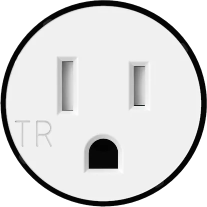
 Design with 220V Outlet in Cirkit Designer
Introduction
A 220V outlet is a power receptacle designed to supply electrical power at 220 volts. It is commonly used for high-power appliances and equipment, such as air conditioners, electric dryers, ovens, and industrial machinery. These outlets are prevalent in residential, commercial, and industrial settings where higher voltage is required to operate energy-intensive devices efficiently.
Explore Projects Built with 220V Outlet
 Open Project in Cirkit Designer
 Open Project in Cirkit Designer
 Open Project in Cirkit Designer
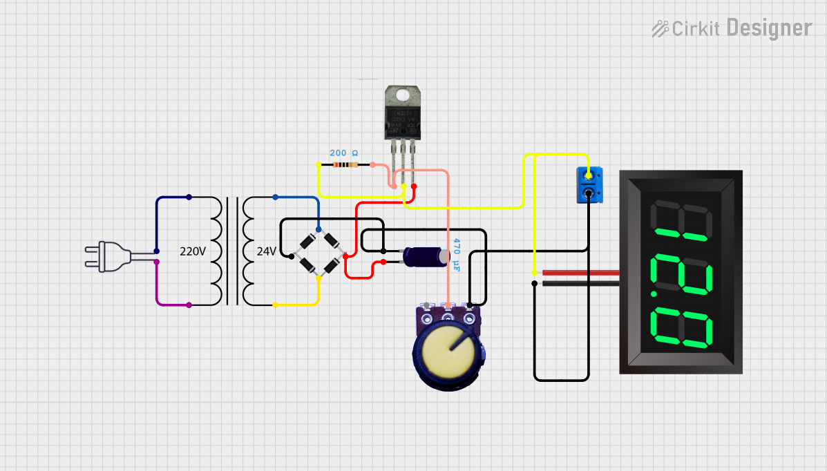 Open Project in Cirkit Designer
Explore Projects Built with 220V Outlet
Open Project in Cirkit DesignerOpen Project in Cirkit DesignerOpen Project in Cirkit DesignerOpen Project in Cirkit DesignerCommon Applications and Use Cases
- Powering large household appliances (e.g., ovens, dryers, and water heaters)
- Industrial equipment and machinery
- Air conditioning systems
- Electric vehicle (EV) charging stations
- High-power tools in workshops
Technical Specifications
Key Technical Details
| Parameter | Specification |
|---|---|
| Voltage Rating | 220V AC |
| Current Rating | Typically 15A, 20A, or 30A |
| Frequency | 50Hz or 60Hz (region-dependent) |
| Number of Pins | 3 or 4 (depending on the outlet type) |
| Grounding | Yes (ground pin included) |
| Material | Heat-resistant plastic and metal |
| Mounting Style | Wall-mounted or flush-mounted |
Pin Configuration and Descriptions
For a 3-Pin 220V Outlet:
| Pin Name | Description |
|---|---|
| Line (L) | Supplies the live 220V AC voltage |
| Neutral (N) | Returns current to complete the circuit |
| Ground (G) | Provides safety by grounding the circuit |
For a 4-Pin 220V Outlet:
| Pin Name | Description |
|---|---|
| Line 1 (L1) | Supplies one phase of the 220V AC voltage |
| Line 2 (L2) | Supplies the second phase of the 220V AC voltage |
| Neutral (N) | Returns current to complete the circuit |
| Ground (G) | Provides safety by grounding the circuit |
Usage Instructions
How to Use the Component in a Circuit
- Verify Voltage Requirements: Ensure the appliance or device you are connecting is rated for 220V operation.
- Install the Outlet:
- Turn off the power supply at the circuit breaker before installation.
- Connect the wires to the appropriate terminals:
- For a 3-pin outlet: Connect the live wire to the "L" terminal, the neutral wire to the "N" terminal, and the ground wire to the "G" terminal.
- For a 4-pin outlet: Connect the two live wires to "L1" and "L2," the neutral wire to "N," and the ground wire to "G."
- Secure the outlet in the wall box and attach the faceplate.
- Test the Outlet:
- Use a multimeter to verify the voltage between the pins.
- Ensure proper grounding for safety.
- Connect the Appliance: Plug in the appliance or device, ensuring the plug matches the outlet type.
Important Considerations and Best Practices
- Safety First: Always turn off the power supply before working with electrical outlets.
- Use Proper Wiring: Ensure the wires used are rated for the current and voltage of the outlet.
- Grounding: Proper grounding is essential to prevent electrical shocks.
- Compliance: Follow local electrical codes and standards during installation.
- Avoid Overloading: Do not exceed the current rating of the outlet.
Example: Connecting a 220V Outlet to an Arduino-Controlled Relay
If you are using an Arduino to control a 220V appliance via a relay, ensure the relay module is rated for 220V AC. Below is an example code snippet for controlling a relay:
// Arduino code to control a relay for a 220V outlet
const int relayPin = 7; // Pin connected to the relay module

void setup() {
  pinMode(relayPin, OUTPUT); // Set relay pin as output
  digitalWrite(relayPin, LOW); // Ensure relay is off initially
}

void loop() {
  // Turn on the relay (activates the 220V outlet)
  digitalWrite(relayPin, HIGH);
  delay(5000); // Keep the outlet on for 5 seconds

  // Turn off the relay (deactivates the 220V outlet)
  digitalWrite(relayPin, LOW);
  delay(5000); // Keep the outlet off for 5 seconds
}
Note: Always use an optocoupled relay module for safety when working with high voltages. Never directly connect 220V to the Arduino.
Troubleshooting and FAQs
Common Issues Users Might Face
No Power at the Outlet:
- Cause: Loose wiring or tripped circuit breaker.
- Solution: Check the wiring connections and reset the circuit breaker.
Appliance Not Working:
- Cause: Incorrect voltage or damaged appliance.
- Solution: Verify the appliance's voltage rating and test it on another outlet.
Sparks or Burning Smell:
- Cause: Faulty wiring or overloaded outlet.
- Solution: Turn off the power immediately and inspect the wiring. Replace the outlet if necessary.
Multimeter Shows Incorrect Voltage:
- Cause: Faulty multimeter or improper grounding.
- Solution: Test the multimeter on a known good outlet and ensure proper grounding.
Solutions and Tips for Troubleshooting
- Use a circuit tester or multimeter to diagnose electrical issues.
- Ensure all connections are tight and secure.
- If unsure about installation or troubleshooting, consult a licensed electrician.
- Regularly inspect the outlet for signs of wear, damage, or overheating.
By following this documentation, you can safely and effectively use a 220V outlet in your projects or installations.