How to Use Gikfun Multifunction Trigger Delay Time Module Switch Control: Examples, Pinouts, and Specs
Introduction
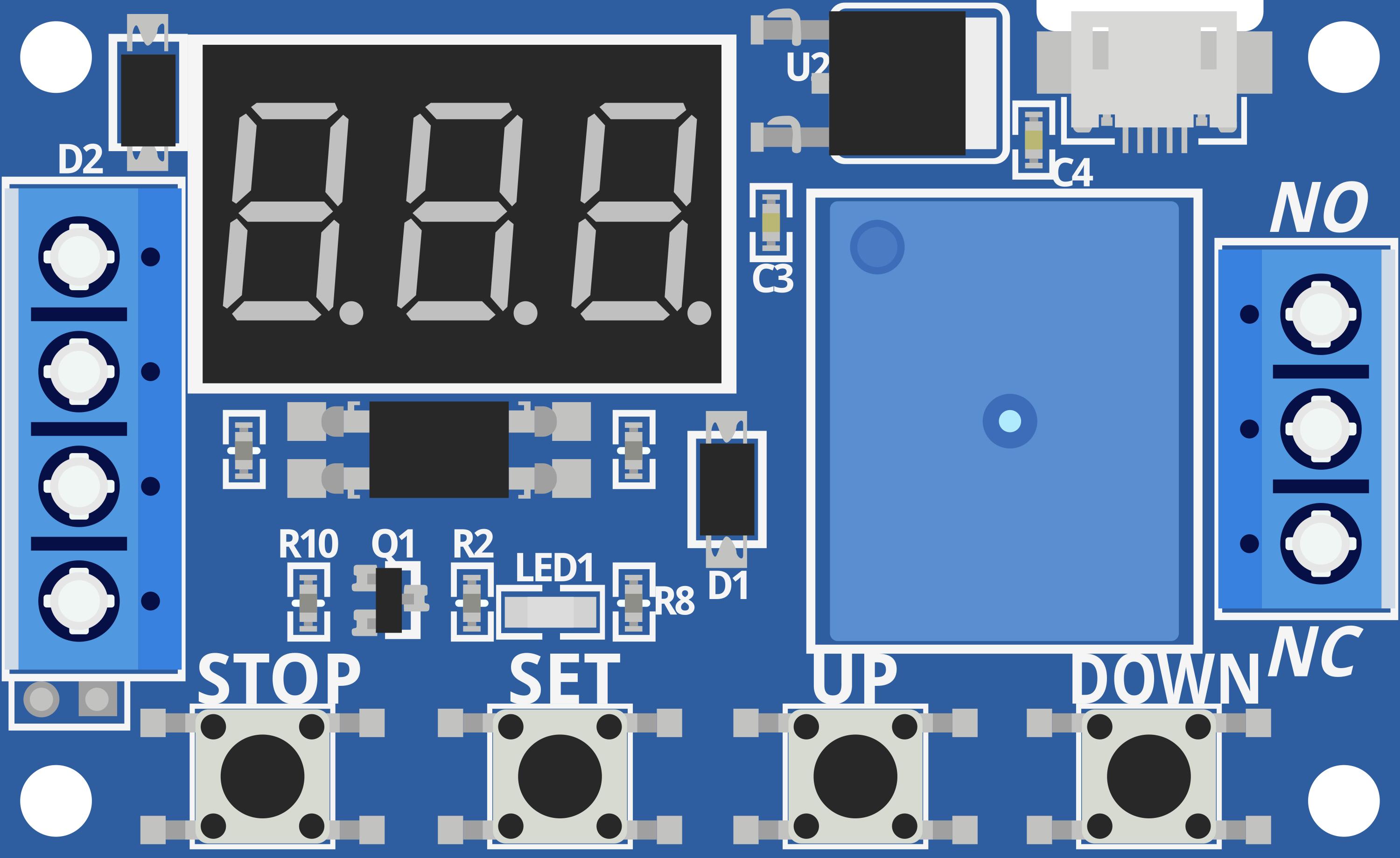
The Gikfun Multifunction Trigger Delay Time Module Switch Control is an electronic timing controller that provides a delay before triggering an event in a circuit. This module is widely used in applications requiring timed operations such as automated control systems, delay timers in lighting systems, and as a pulse generator for stepper motor control.
Explore Projects Built with Gikfun Multifunction Trigger Delay Time Module Switch Control
Explore Projects Built with Gikfun Multifunction Trigger Delay Time Module Switch Control
Common Applications and Use Cases
- Automated lighting control
- Time-delayed switching
- Motor control circuits
- Alarm systems
- Pulse generation for stepper motors
Technical Specifications
Key Technical Details
- Operating Voltage: 5V to 36V DC
- Control Current: 15mA (max)
- Load Current: 10A (max)
- Time Range: 0.1 seconds to 999 minutes adjustable
- Operating Modes: Multiple (including delay on, delay off, and cycling)
Pin Configuration and Descriptions
| Pin Number | Description |
|---|---|
| 1 | VCC (Power Supply Positive) |
| 2 | GND (Power Supply Negative) |
| 3 | IN (Trigger Input) |
| 4 | OUT (Output to Load) |
Usage Instructions
How to Use the Component in a Circuit
Power Supply Connection: Connect the VCC pin to a DC power supply within the range of 5V to 36V, and connect the GND pin to the ground of the power supply.
Load Connection: Connect the device or load you wish to control to the OUT pin. Ensure the load does not exceed the maximum current rating of 10A.
Trigger Input: The IN pin is used to trigger the delay. A low-level signal (close to 0V) on this pin will start the timing sequence.
Setting the Delay Time: Adjust the onboard potentiometer or use external controls to set the desired delay time within the 0.1 seconds to 999 minutes range.
Operating Mode Selection: Choose the appropriate operating mode for your application by adjusting the onboard jumpers or dip switches.
Important Considerations and Best Practices
- Always verify that the power supply voltage matches the module's requirements.
- Do not exceed the maximum load current to prevent damage to the module.
- Use a flyback diode when controlling inductive loads to protect the module from voltage spikes.
- Ensure proper heat dissipation if the module is expected to handle high currents for extended periods.
Troubleshooting and FAQs
Common Issues Users Might Face
- Module Does Not Activate: Check the power supply connections and ensure the trigger input is receiving a low-level signal.
- Unexpected Timing Delays: Verify the delay time settings and ensure the potentiometer is functioning correctly.
- Load Does Not Turn On/Off: Ensure the load current does not exceed the module's maximum rating and check the connections to the OUT pin.
Solutions and Tips for Troubleshooting
- Double-check all connections, including power supply, trigger input, and load.
- Test the module with a known working load to rule out issues with the connected device.
- If the module is unresponsive, disconnect the power supply and check for any visible damage or loose components.
FAQs
Q: Can I use this module with an Arduino? A: Yes, the module can be controlled using an Arduino by connecting the trigger input to an Arduino digital pin.
Q: What is the maximum load I can connect to this module? A: The maximum load should not exceed 10A.
Q: How do I adjust the delay time? A: The delay time can be adjusted using the onboard potentiometer or through external controls if available.
Q: Is it possible to power the module with a 5V USB power supply? A: Yes, as long as the power supply can provide sufficient current and falls within the 5V to 36V range.
Example Arduino Code
// Example code to control the Gikfun Multifunction Trigger Delay Time Module
// with an Arduino UNO

const int triggerPin = 7; // Connect to the IN pin of the module

void setup() {
  pinMode(triggerPin, OUTPUT);
  Serial.begin(9600);
}

void loop() {
  digitalWrite(triggerPin, LOW); // Trigger the delay module
  Serial.println("Module triggered, delay started.");
  delay(1000); // Wait for 1 second
  digitalWrite(triggerPin, HIGH); // Reset the trigger
  delay(5000); // Wait for 5 seconds before triggering again
}
Note: The above code is a simple example to demonstrate how to trigger the delay module using an Arduino. Adjust the delay() values as needed for your specific application. Always ensure that the Arduino's digital pin connected to the module's trigger input is set to HIGH to keep the module in a reset state when not triggering.