How to Use PWM Relay: Examples, Pinouts, and Specs
Introduction
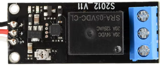
A PWM (Pulse Width Modulation) relay is an electromechanical switch designed to control the power delivered to a load using PWM signals. By varying the duty cycle of the PWM signal, the relay enables precise control over parameters such as motor speed, LED brightness, or heating element intensity. This makes it an efficient and versatile component for applications requiring variable power control.
Explore Projects Built with PWM Relay
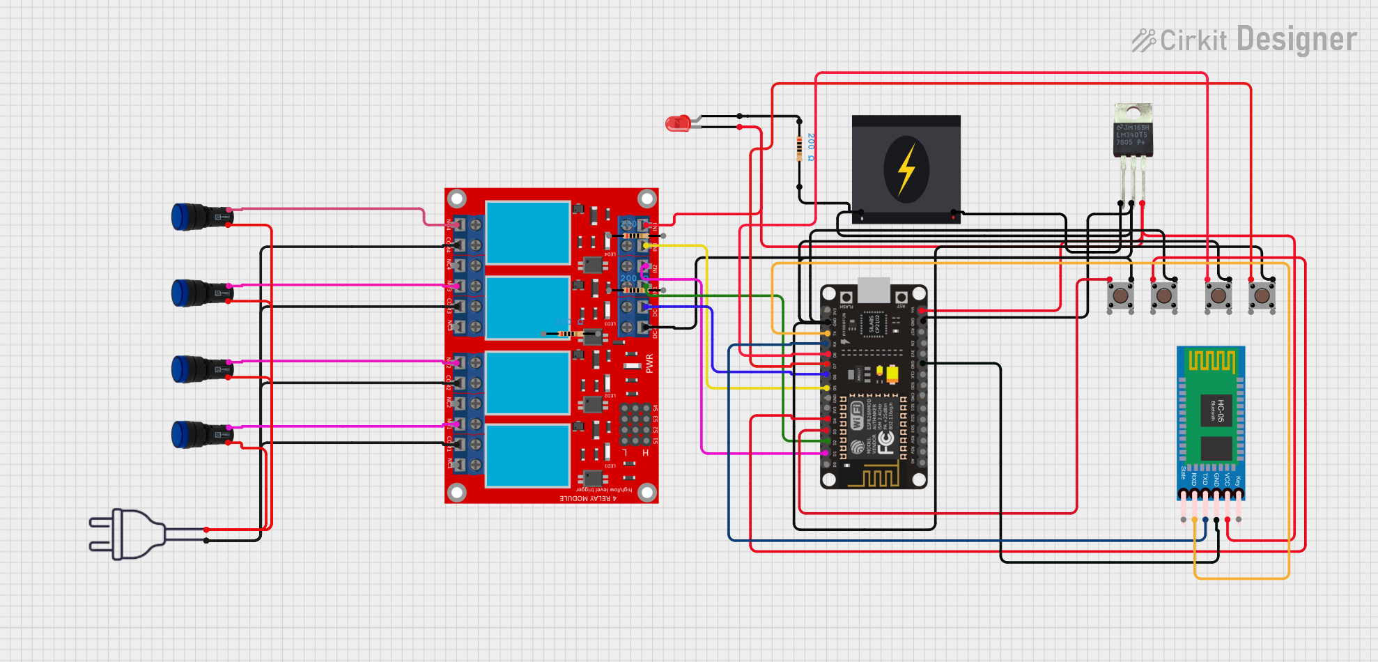

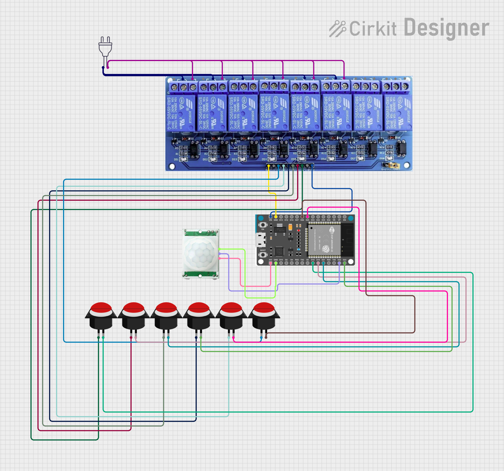
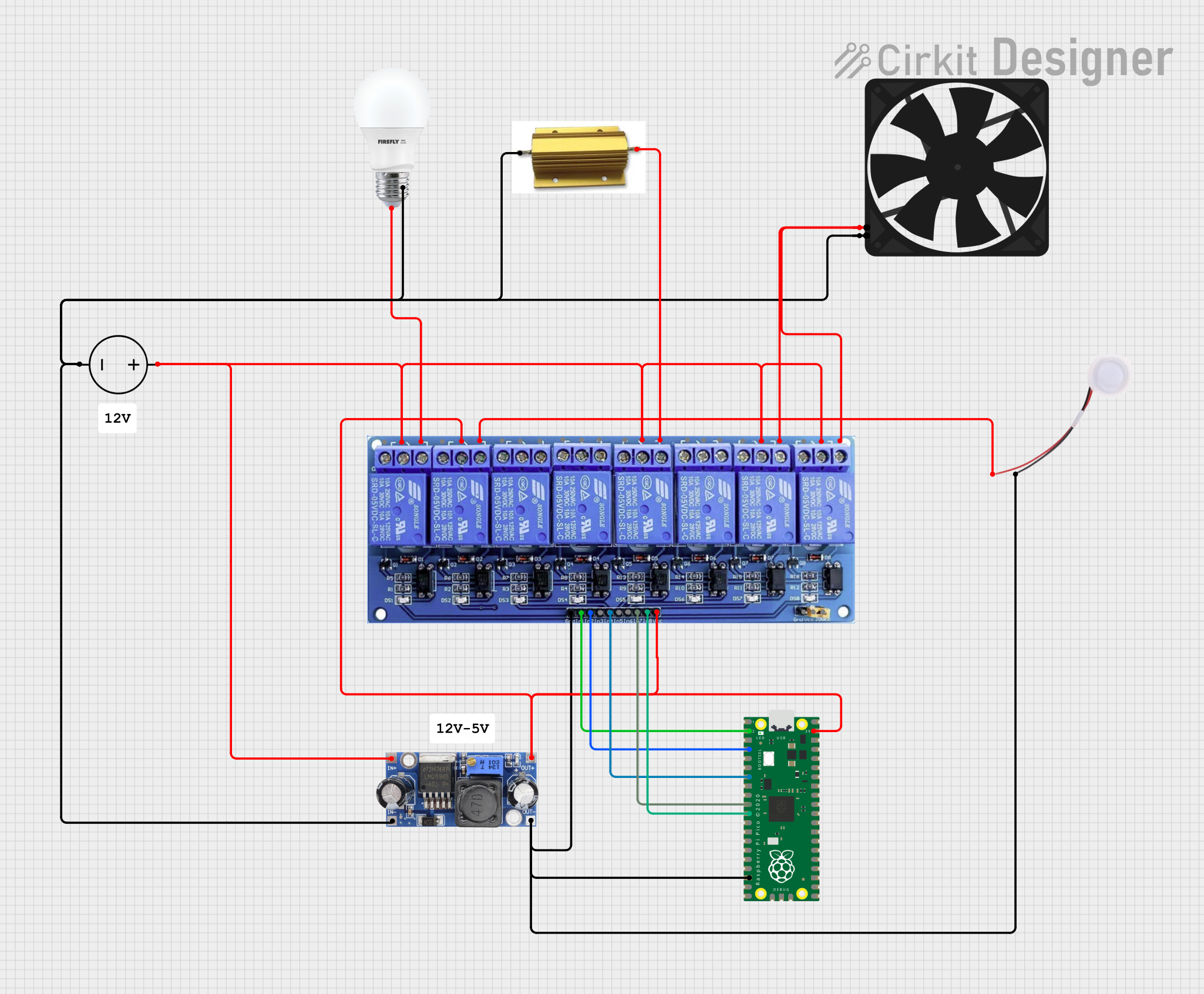
Explore Projects Built with PWM Relay
Common Applications and Use Cases
- Motor speed control in robotics and automation systems
- LED dimming for lighting applications
- Temperature regulation in heating systems
- Power control in industrial equipment
- Battery charging systems with controlled current delivery
Technical Specifications
Below are the key technical details and pin configuration for a typical PWM relay:
Key Technical Details
| Parameter | Value |
|---|---|
| Operating Voltage | 5V, 12V, or 24V (model-dependent) |
| Control Signal Voltage | 3.3V or 5V (logic level) |
| PWM Frequency Range | 100 Hz to 10 kHz |
| Maximum Load Current | 10A (varies by model) |
| Contact Type | SPDT (Single Pole Double Throw) |
| Duty Cycle Range | 0% to 100% |
| Isolation | Optocoupler-based isolation |
| Operating Temperature | -20°C to 85°C |
Pin Configuration and Descriptions
| Pin Name | Description |
|---|---|
| VCC | Power supply input for the relay module (5V, 12V, or 24V depending on model). |
| GND | Ground connection for the relay module. |
| PWM_IN | Input pin for the PWM signal (3.3V or 5V logic level). |
| NO (Normally Open) | Normally open contact for the load connection. |
| NC (Normally Closed) | Normally closed contact for the load connection. |
| COM | Common terminal for the load connection. |
Usage Instructions
How to Use the PWM Relay in a Circuit
- Power the Relay Module: Connect the VCC and GND pins to the appropriate power supply (e.g., 5V, 12V, or 24V, depending on the relay model).
- Connect the Load:
- For devices that should be powered when the relay is active, connect the load between the NO (Normally Open) and COM (Common) terminals.
- For devices that should be powered when the relay is inactive, connect the load between the NC (Normally Closed) and COM terminals.
- Provide a PWM Signal: Connect the PWM_IN pin to a microcontroller or PWM signal generator. Ensure the signal voltage matches the relay's logic level (3.3V or 5V).
- Adjust the Duty Cycle: Use the PWM signal to control the relay's switching behavior. A higher duty cycle increases the power delivered to the load, while a lower duty cycle reduces it.
Important Considerations and Best Practices
- Voltage Compatibility: Ensure the relay's operating voltage matches your power supply and control signal voltage.
- Current Rating: Verify that the relay's maximum load current rating is sufficient for your application.
- PWM Frequency: Use a PWM frequency within the relay's specified range (100 Hz to 10 kHz) for optimal performance.
- Isolation: The relay provides electrical isolation between the control circuit and the load. However, ensure proper grounding to avoid noise or interference.
- Heat Dissipation: For high-current loads, consider adding a heatsink or cooling mechanism to prevent overheating.
Example: Using a PWM Relay with Arduino UNO
Below is an example of how to control a PWM relay using an Arduino UNO to dim an LED:
// Define the PWM pin connected to the relay's PWM_IN pin
const int pwmPin = 9; // PWM-capable pin on Arduino UNO

void setup() {
  pinMode(pwmPin, OUTPUT); // Set the PWM pin as an output
}

void loop() {
  // Gradually increase brightness
  for (int dutyCycle = 0; dutyCycle <= 255; dutyCycle++) {
    analogWrite(pwmPin, dutyCycle); // Write PWM signal to the relay
    delay(10); // Small delay for smooth transition
  }

  // Gradually decrease brightness
  for (int dutyCycle = 255; dutyCycle >= 0; dutyCycle--) {
    analogWrite(pwmPin, dutyCycle); // Write PWM signal to the relay
    delay(10); // Small delay for smooth transition
  }
}
Troubleshooting and FAQs
Common Issues and Solutions
Relay Not Switching Properly
- Cause: Incorrect PWM signal voltage or frequency.
- Solution: Verify that the PWM signal matches the relay's logic level (3.3V or 5V) and is within the specified frequency range.
Load Not Receiving Power
- Cause: Incorrect wiring of the load to the relay terminals.
- Solution: Double-check the connections to the NO, NC, and COM terminals based on your desired behavior.
Overheating
- Cause: Exceeding the relay's maximum current rating.
- Solution: Ensure the load current does not exceed the relay's rated capacity. Use a heatsink if necessary.
PWM Signal Interference
- Cause: Electrical noise or improper grounding.
- Solution: Use proper grounding and shielded cables for the PWM signal.
FAQs
Q: Can I use a PWM relay with a 3.3V microcontroller like ESP32?
A: Yes, as long as the relay supports 3.3V logic levels for the PWM_IN pin.
Q: What happens if I use a PWM frequency outside the specified range?
A: The relay may not operate correctly, leading to erratic switching or reduced efficiency.
Q: Can I control multiple relays with a single microcontroller?
A: Yes, as long as you have enough PWM-capable pins and the microcontroller can handle the required processing load.
Q: Is the relay suitable for AC loads?
A: Yes, but ensure the relay's contact ratings are compatible with the AC voltage and current of your load.