
How to Use UART 2102 Module 6-pin: Examples, Pinouts, and Specs
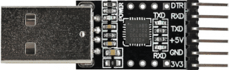
 Design with UART 2102 Module 6-pin in Cirkit Designer
Introduction
The UART 2102 Module (Manufacturer Part ID: CP2102) is a compact and reliable serial communication module designed to facilitate UART (Universal Asynchronous Receiver-Transmitter) communication. It is widely used for interfacing microcontrollers, such as Arduino or Raspberry Pi, with other devices like sensors, computers, or embedded systems. The module's 6-pin configuration ensures straightforward integration into a variety of electronic projects, making it a popular choice for both hobbyists and professionals.
Explore Projects Built with UART 2102 Module 6-pin
 Open Project in Cirkit Designer
 Open Project in Cirkit Designer
 Open Project in Cirkit Designer
 Open Project in Cirkit Designer
Explore Projects Built with UART 2102 Module 6-pin
Open Project in Cirkit DesignerOpen Project in Cirkit DesignerOpen Project in Cirkit DesignerOpen Project in Cirkit DesignerCommon Applications
- USB-to-serial communication for microcontrollers
- Debugging and programming embedded systems
- Interfacing sensors or peripherals with UART communication
- Data logging and serial communication with PCs
- Prototyping and testing serial communication protocols
Technical Specifications
The UART 2102 Module is based on the CP2102 chipset, which provides robust and efficient UART communication. Below are the key technical details:
Key Specifications
- Chipset: CP2102
- Communication Protocol: UART
- Operating Voltage: 3.3V or 5V (selectable)
- Baud Rate: Up to 1 Mbps
- USB Interface: USB 2.0 Full-Speed
- Driver Support: Windows, macOS, Linux
- Operating Temperature: -40°C to +85°C
- Dimensions: Compact form factor for easy integration
Pin Configuration and Descriptions
The module features a 6-pin header for easy connection. Below is the pinout and description:
| Pin | Name | Description |
|---|---|---|
| 1 | GND | Ground connection |
| 2 | VCC | Power input (3.3V or 5V, depending on the module configuration) |
| 3 | TXD | Transmit Data (UART output, connects to RXD of the target device) |
| 4 | RXD | Receive Data (UART input, connects to TXD of the target device) |
| 5 | DTR | Data Terminal Ready (used for resetting microcontrollers like Arduino) |
| 6 | RTS | Request to Send (optional, used for hardware flow control in some applications) |
Usage Instructions
How to Use the UART 2102 Module in a Circuit
- Power the Module: Connect the
VCCpin to a 3.3V or 5V power source, and theGNDpin to the ground of your circuit. - Connect UART Lines:
- Connect the
TXDpin of the module to theRXDpin of the target device. - Connect the
RXDpin of the module to theTXDpin of the target device.
- Connect the
- Optional Connections:
- Use the
DTRpin for resetting microcontrollers during programming. - Connect the
RTSpin if hardware flow control is required.
- Use the
- USB Connection: Plug the module into a computer using a USB cable. Ensure the appropriate drivers for the CP2102 chipset are installed on your operating system.
- Configure Communication: Set the baud rate and other UART parameters (e.g., parity, stop bits) in your software or terminal application.
Important Considerations and Best Practices
- Voltage Compatibility: Ensure the target device operates at the same voltage level as the module (3.3V or 5V).
- Driver Installation: Download and install the CP2102 drivers from the manufacturer's website if your operating system does not automatically recognize the module.
- Avoid Cross-Talk: Keep the UART lines (TXD and RXD) short to minimize noise and interference.
- Check Connections: Double-check the pin connections to avoid damaging the module or the target device.
Example: Connecting to an Arduino UNO
Below is an example of how to use the UART 2102 Module to communicate with an Arduino UNO. The module can be used to upload code or send/receive serial data.
Wiring Diagram
| UART 2102 Pin | Arduino UNO Pin |
|---|---|
| GND | GND |
| VCC | 5V |
| TXD | RX (Pin 0) |
| RXD | TX (Pin 1) |
| DTR | RESET |
Arduino Code Example
// Example code to send data from Arduino to a PC via UART 2102 Module
void setup() {
  Serial.begin(9600); // Initialize UART communication at 9600 baud
  delay(1000);        // Wait for the serial connection to stabilize
  Serial.println("UART 2102 Module Test"); // Send a test message
}

void loop() {
  Serial.println("Hello, World!"); // Send data repeatedly
  delay(1000);                    // Wait 1 second between messages
}
Troubleshooting and FAQs
Common Issues and Solutions
Module Not Recognized by PC:
- Ensure the USB cable is functional and properly connected.
- Install the CP2102 drivers from the manufacturer's website.
- Try a different USB port or computer.
No Data Transmission:
- Verify the TXD and RXD connections between the module and the target device.
- Check the baud rate and UART settings in your software.
- Ensure the target device is powered and operational.
Microcontroller Not Resetting:
- Confirm the
DTRpin is connected to theRESETpin of the microcontroller. - Check for proper driver installation and configuration.
- Confirm the
Data Corruption or Noise:
- Use shorter wires for UART connections to reduce interference.
- Ensure the baud rate is supported by both the module and the target device.
FAQs
Q: Can the UART 2102 Module be used with 3.3V devices?
A: Yes, the module supports both 3.3V and 5V operation. Ensure theVCCpin is connected to the appropriate voltage.Q: Is hardware flow control mandatory?
A: No, hardware flow control (RTS/CTS) is optional and only required for specific applications.Q: Where can I download the CP2102 drivers?
A: Drivers are available on the manufacturer's website or through your operating system's update utility.Q: Can I use this module for programming ESP8266 or ESP32?
A: Yes, the module is compatible with ESP8266 and ESP32. Use theDTRpin for automatic resetting during programming.
This documentation provides a comprehensive guide to using the UART 2102 Module (CP2102). For further assistance, refer to the manufacturer's datasheet or support resources.