Cirkit Designer Logo
Cirkit Designer
Your all-in-one circuit design IDE
Home / 
Component Documentation

How to Use RP2040: Examples, Pinouts, and Specs

Image of RP2040
Cirkit Designer LogoDesign with RP2040 in Cirkit Designer

Introduction

The RP2040 is a high-performance microcontroller chip designed by Raspberry Pi and manufactured by Core Board. It features a dual-core ARM Cortex-M0+ processor, 264KB of SRAM, and a rich set of peripherals, making it an excellent choice for a variety of embedded applications. Its low power consumption and flexible I/O options make it ideal for projects ranging from IoT devices to robotics and consumer electronics.

Explore Projects Built with RP2040

Use Cirkit Designer to design, explore, and prototype these projects online. Some projects support real-time simulation. Click "Open Project" to start designing instantly!
Optiplex Micro and PoE Camera Surveillance System with Ethernet Switching
Image of Engine Mounts Wiring: A project utilizing RP2040 in a practical application
This circuit describes a networked system where an Optiplex Micro computer is powered by a PC Power Supply and connected to a PC Screen via HDMI for display output. The computer is networked through an Ethernet Switch, which also connects to two PoE Cameras and a Toyopuc PLC. The Ethernet Switch is powered by a PoE PSU 48V DC, and all AC-powered devices are connected to a common 220V AC source.
Cirkit Designer LogoOpen Project in Cirkit Designer
Dual Microcontroller Integration with Arduino Micro Pro and RP2040 Zero for Enhanced I/O Control
Image of RP2040MacroKey: A project utilizing RP2040 in a practical application
This circuit integrates an Arduino Micro Pro and an RP2040 Zero microcontroller, interconnected to share power and ground, as well as several GPIO pins. The RP2040 Zero is programmed with a basic setup and loop structure, indicating it is ready for further development. The design suggests a collaborative processing or sensor data sharing application between the two microcontrollers.
Cirkit Designer LogoOpen Project in Cirkit Designer
Battery-Powered Smart Light with Proximity Sensor and OLED Display using Adafruit QT Py RP2040
Image of lab: A project utilizing RP2040 in a practical application
This circuit is a portable, battery-powered system featuring an Adafruit QT Py RP2040 microcontroller that interfaces with an OLED display, a proximity sensor, an accelerometer, and an RGB LED strip. The system is powered by a lithium-ion battery with a step-up boost converter to provide 5V for the LED strip, and it includes a toggle switch for power control. The microcontroller communicates with the sensors and display via I2C.
Cirkit Designer LogoOpen Project in Cirkit Designer
Satellite Compass and Network-Integrated GPS Data Processing System
Image of GPS 시스템 측정 구성도_241016: A project utilizing RP2040 in a practical application
This circuit comprises a satellite compass, a mini PC, two GPS antennas, power supplies, a network switch, media converters, and an atomic rubidium clock. The satellite compass is powered by a triple output DC power supply and interfaces with an RS232 splitter for 1PPS signals. The mini PCs are connected to the USRP B200 devices via USB for data and power, and to media converters via Ethernet, which in turn connect to a network switch using fiber optic links. The antennas are connected to the USRP B200s through RF directional couplers, and the atomic clock provides a 1PPS input to the RS232 splitter.
Cirkit Designer LogoOpen Project in Cirkit Designer

Explore Projects Built with RP2040

Use Cirkit Designer to design, explore, and prototype these projects online. Some projects support real-time simulation. Click "Open Project" to start designing instantly!
Image of Engine Mounts Wiring: A project utilizing RP2040 in a practical application
Optiplex Micro and PoE Camera Surveillance System with Ethernet Switching
This circuit describes a networked system where an Optiplex Micro computer is powered by a PC Power Supply and connected to a PC Screen via HDMI for display output. The computer is networked through an Ethernet Switch, which also connects to two PoE Cameras and a Toyopuc PLC. The Ethernet Switch is powered by a PoE PSU 48V DC, and all AC-powered devices are connected to a common 220V AC source.
Cirkit Designer LogoOpen Project in Cirkit Designer
Image of RP2040MacroKey: A project utilizing RP2040 in a practical application
Dual Microcontroller Integration with Arduino Micro Pro and RP2040 Zero for Enhanced I/O Control
This circuit integrates an Arduino Micro Pro and an RP2040 Zero microcontroller, interconnected to share power and ground, as well as several GPIO pins. The RP2040 Zero is programmed with a basic setup and loop structure, indicating it is ready for further development. The design suggests a collaborative processing or sensor data sharing application between the two microcontrollers.
Cirkit Designer LogoOpen Project in Cirkit Designer
Image of lab: A project utilizing RP2040 in a practical application
Battery-Powered Smart Light with Proximity Sensor and OLED Display using Adafruit QT Py RP2040
This circuit is a portable, battery-powered system featuring an Adafruit QT Py RP2040 microcontroller that interfaces with an OLED display, a proximity sensor, an accelerometer, and an RGB LED strip. The system is powered by a lithium-ion battery with a step-up boost converter to provide 5V for the LED strip, and it includes a toggle switch for power control. The microcontroller communicates with the sensors and display via I2C.
Cirkit Designer LogoOpen Project in Cirkit Designer
Image of GPS 시스템 측정 구성도_241016: A project utilizing RP2040 in a practical application
Satellite Compass and Network-Integrated GPS Data Processing System
This circuit comprises a satellite compass, a mini PC, two GPS antennas, power supplies, a network switch, media converters, and an atomic rubidium clock. The satellite compass is powered by a triple output DC power supply and interfaces with an RS232 splitter for 1PPS signals. The mini PCs are connected to the USRP B200 devices via USB for data and power, and to media converters via Ethernet, which in turn connect to a network switch using fiber optic links. The antennas are connected to the USRP B200s through RF directional couplers, and the atomic clock provides a 1PPS input to the RS232 splitter.
Cirkit Designer LogoOpen Project in Cirkit Designer

Common Applications and Use Cases

  • IoT (Internet of Things) devices
  • Robotics and automation systems
  • Wearable technology
  • Data logging and sensor interfacing
  • Educational and prototyping platforms
  • Audio processing and signal control

Technical Specifications

The RP2040 microcontroller is packed with features that make it versatile and powerful for embedded systems. Below are its key technical specifications:

Key Technical Details

Specification Value
Processor Dual-core ARM Cortex-M0+
Clock Speed Up to 133 MHz
SRAM 264 KB
Flash Memory External QSPI flash (up to 16 MB)
GPIO Pins 30 (4 can be used as analog inputs)
Communication Interfaces I2C, SPI, UART, USB 1.1 (Device/Host)
PWM Channels 16
ADC Resolution 12-bit
Operating Voltage 1.8V to 3.3V
Power Supply Options USB, Li-Po battery, or external power
Temperature Range -20°C to +85°C

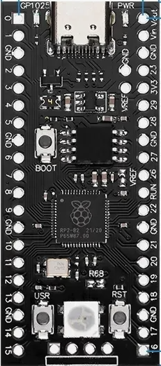
Pin Configuration and Descriptions

The RP2040 has 30 GPIO pins, each of which can be configured for multiple functions. Below is a table summarizing the pin configuration:

Pin Number Default Function Alternate Functions
GPIO0 Digital I/O UART TX, I2C SDA, SPI CS
GPIO1 Digital I/O UART RX, I2C SCL, SPI CLK
GPIO2 Digital I/O PWM, ADC Input
GPIO3 Digital I/O PWM, ADC Input
GPIO4 Digital I/O PWM, ADC Input
GPIO5 Digital I/O PWM, ADC Input
GPIO6-29 Digital I/O Various alternate functions (PWM, I2C)

For a complete pinout diagram, refer to the official RP2040 datasheet.

Usage Instructions

The RP2040 is designed to be easy to use in a variety of embedded systems. Below are the steps and best practices for integrating it into your project.

How to Use the RP2040 in a Circuit

  1. Powering the RP2040:

    • Connect a 5V power source via USB or use an external 3.3V regulator for direct power.
    • Ensure proper decoupling capacitors are placed near the power pins to reduce noise.
  2. Connecting Peripherals:

    • Use GPIO pins for digital I/O or configure them for alternate functions like UART, SPI, or I2C.
    • For analog inputs, connect sensors to GPIO pins 26-29, which support ADC functionality.
  3. Programming the RP2040:

    • The RP2040 can be programmed using the C/C++ SDK or MicroPython.
    • To upload code, hold the BOOTSEL button while connecting the board to your computer via USB. The RP2040 will appear as a mass storage device. Drag and drop the firmware file to program it.

Important Considerations and Best Practices

  • Voltage Levels: Ensure all connected peripherals operate within the RP2040's voltage range (1.8V to 3.3V).
  • Clock Configuration: Use the internal crystal oscillator for accurate timing or configure an external clock source if needed.
  • Heat Management: While the RP2040 is efficient, ensure proper ventilation or heat dissipation for high-performance applications.

Example Code for Arduino UNO Integration

Although the RP2040 is not directly compatible with Arduino UNO, it can communicate with it via I2C or UART. Below is an example of using the RP2040 as an I2C slave device:

// RP2040 I2C Slave Example
#include <Wire.h>

// Define the I2C address for the RP2040
#define SLAVE_ADDRESS 0x08

void setup() {
  Wire.begin(SLAVE_ADDRESS); // Initialize as I2C slave
  Wire.onRequest(requestEvent); // Register request event handler
  Wire.onReceive(receiveEvent); // Register receive event handler
  Serial.begin(9600); // Initialize serial communication for debugging
}

void loop() {
  // Main loop does nothing; events are handled via interrupts
}

// Function to handle data requests from the master
void requestEvent() {
  Wire.write("Hello from RP2040!"); // Send data to the master
}

// Function to handle data received from the master
void receiveEvent(int bytes) {
  while (Wire.available()) {
    char c = Wire.read(); // Read incoming data
    Serial.print(c); // Print received data to the serial monitor
  }
}

Troubleshooting and FAQs

Common Issues and Solutions

  1. RP2040 Not Detected by Computer:

    • Ensure the BOOTSEL button is held down while connecting the board via USB.
    • Check the USB cable for data transfer capability (some cables are power-only).
  2. Program Upload Fails:

    • Verify that the firmware file is compatible with the RP2040.
    • Ensure the board is in bootloader mode before uploading.
  3. Peripheral Communication Issues:

    • Double-check wiring and ensure proper pull-up resistors are used for I2C.
    • Verify that the GPIO pins are configured correctly for the desired function.

FAQs

Q: Can the RP2040 run Python code?
A: Yes, the RP2040 supports MicroPython, allowing you to write and execute Python scripts directly on the chip.

Q: What is the maximum clock speed of the RP2040?
A: The RP2040 can operate at a maximum clock speed of 133 MHz.

Q: How much external flash memory can the RP2040 support?
A: The RP2040 supports up to 16 MB of external QSPI flash memory.

By following this documentation, you can effectively integrate and utilize the RP2040 in your embedded projects. For more detailed information, refer to the official datasheet and SDK documentation.