How to Use ESP32Wroom32: Examples, Pinouts, and Specs
Introduction
The ESP32 Wroom 32 is a powerful microcontroller module that integrates Wi-Fi and Bluetooth capabilities, making it a versatile choice for Internet of Things (IoT) applications. It features dual-core processing, a rich set of peripherals, and low power consumption, enabling it to handle complex tasks while maintaining energy efficiency. The module is widely used in smart devices, wireless communication systems, and automation projects.
Explore Projects Built with ESP32Wroom32


Explore Projects Built with ESP32Wroom32
Common Applications and Use Cases
- Smart home devices (e.g., smart lights, thermostats)
- IoT sensors and data loggers
- Wireless communication hubs
- Wearable devices
- Robotics and automation systems
- Industrial IoT applications
Technical Specifications
The ESP32 Wroom 32 module is built around the ESP32-D0WDQ6 chip and offers the following key specifications:
| Specification | Details |
|---|---|
| Microcontroller | ESP32-D0WDQ6 |
| CPU | Dual-core Xtensa® 32-bit LX6, up to 240 MHz |
| Flash Memory | 4 MB (default, can vary by module version) |
| SRAM | 520 KB |
| Wireless Connectivity | Wi-Fi 802.11 b/g/n, Bluetooth v4.2 BR/EDR and BLE |
| Operating Voltage | 3.0V to 3.6V |
| GPIO Pins | 34 |
| ADC Channels | 18 (12-bit resolution) |
| DAC Channels | 2 |
| Communication Interfaces | UART, SPI, I2C, I2S, CAN, PWM |
| Power Consumption | Ultra-low power consumption in deep sleep mode (as low as 10 µA) |
| Operating Temperature | -40°C to +85°C |
| Dimensions | 18 mm x 25.5 mm |
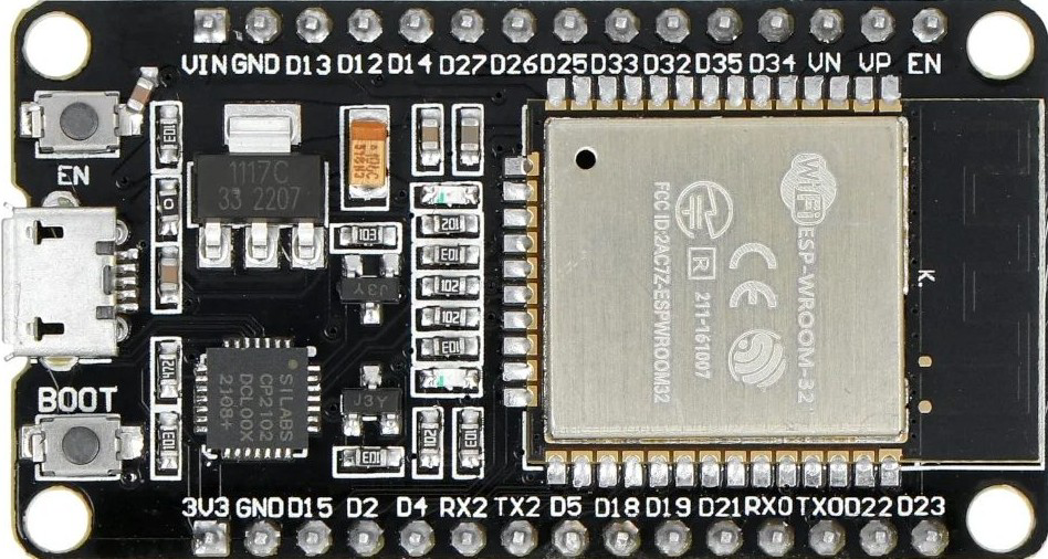
Pin Configuration and Descriptions
The ESP32 Wroom 32 module has 38 pins, with the following key pin assignments:
| Pin Number | Pin Name | Description |
|---|---|---|
| 1 | EN | Enable pin. Active high. Resets the chip when pulled low. |
| 2 | IO0 | GPIO0. Used to enter bootloader mode during programming. |
| 3 | IO1 (TX0) | GPIO1. UART0 TX pin. |
| 4 | IO3 (RX0) | GPIO3. UART0 RX pin. |
| 5 | IO4 | GPIO4. General-purpose I/O pin. |
| 6 | IO5 | GPIO5. General-purpose I/O pin. |
| 7 | IO12 | GPIO12. Can be used as an ADC or touch sensor input. |
| 8 | IO13 | GPIO13. Can be used as an ADC or touch sensor input. |
| 9 | IO14 | GPIO14. Can be used as an ADC or touch sensor input. |
| 10 | IO15 | GPIO15. Can be used as an ADC or touch sensor input. |
| 11 | IO16 | GPIO16. General-purpose I/O pin. |
| 12 | IO17 | GPIO17. General-purpose I/O pin. |
| 13 | GND | Ground pin. |
| 14 | 3V3 | 3.3V power supply input. |
| 15 | VIN | Input voltage (5V). |
Note: Not all GPIO pins are available for general use. Some are reserved for specific functions or have restrictions.
Usage Instructions
How to Use the ESP32 Wroom 32 in a Circuit
Powering the Module:
- Connect the
3V3pin to a 3.3V power source. - Alternatively, use the
VINpin to supply 5V, which will be regulated internally. - Ensure the
GNDpin is connected to the ground of your circuit.
- Connect the
Programming the Module:
- Use a USB-to-serial adapter to connect the ESP32 to your computer.
- Connect the
TXandRXpins of the adapter to theRX0andTX0pins of the ESP32, respectively. - Pull the
IO0pin low (connect to GND) to enter bootloader mode for programming.
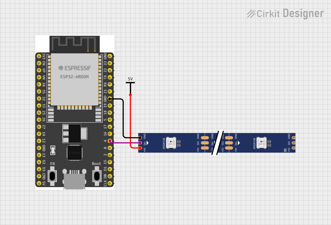
Connecting Peripherals:
- Use the GPIO pins to connect sensors, actuators, or other peripherals.
- For analog inputs, use the ADC pins (e.g.,
IO12,IO13). - For PWM signals, use any GPIO pin capable of PWM output.
Wi-Fi and Bluetooth Setup:
- Configure Wi-Fi and Bluetooth settings in your code to enable wireless communication.
Important Considerations and Best Practices
- Voltage Levels: The ESP32 operates at 3.3V logic levels. Avoid connecting 5V signals directly to its GPIO pins.
- Boot Mode: Ensure the
IO0pin is pulled low during programming and released afterward. - Power Supply: Use a stable power source to avoid unexpected resets or malfunctions.
- Heat Management: The module may heat up during operation. Ensure proper ventilation or heat dissipation.
Example Code for Arduino UNO Integration
Below is an example of using the ESP32 Wroom 32 to connect to a Wi-Fi network:
#include <WiFi.h> // Include the Wi-Fi library for ESP32

const char* ssid = "Your_SSID";       // Replace with your Wi-Fi network name
const char* password = "Your_Password"; // Replace with your Wi-Fi password

void setup() {
  Serial.begin(115200); // Initialize serial communication at 115200 baud
  delay(1000);          // Wait for a second to stabilize

  Serial.println("Connecting to Wi-Fi...");
  WiFi.begin(ssid, password); // Start Wi-Fi connection

  while (WiFi.status() != WL_CONNECTED) {
    delay(500); // Wait for connection
    Serial.print(".");
  }

  Serial.println("\nWi-Fi connected!");
  Serial.print("IP Address: ");
  Serial.println(WiFi.localIP()); // Print the assigned IP address
}

void loop() {
  // Add your main code here
}
Note: Replace
Your_SSIDandYour_Passwordwith your Wi-Fi credentials.
Troubleshooting and FAQs
Common Issues
ESP32 Not Connecting to Wi-Fi:
- Cause: Incorrect SSID or password.
- Solution: Double-check your Wi-Fi credentials in the code.
Module Not Detected by Computer:
- Cause: Missing USB-to-serial driver or faulty connection.
- Solution: Install the correct driver for your USB-to-serial adapter and check the wiring.
Frequent Resets or Instability:
- Cause: Insufficient power supply.
- Solution: Use a stable 3.3V or 5V power source with adequate current capacity.
GPIO Pin Not Responding:
- Cause: Pin may be reserved for internal functions.
- Solution: Refer to the pin configuration table to ensure the pin is available for general use.
FAQs
Can the ESP32 Wroom 32 operate on 5V logic?
No, the ESP32 operates at 3.3V logic levels. Use a level shifter if interfacing with 5V devices.What is the maximum Wi-Fi range of the ESP32?
The range depends on environmental factors but typically extends up to 100 meters in open space.Can I use the ESP32 with Arduino IDE?
Yes, the ESP32 is fully compatible with the Arduino IDE. Install the ESP32 board package to get started.How do I reduce power consumption?
Use the deep sleep mode to minimize power usage when the module is idle.