How to Use Water Sensor: Examples, Pinouts, and Specs
Introduction
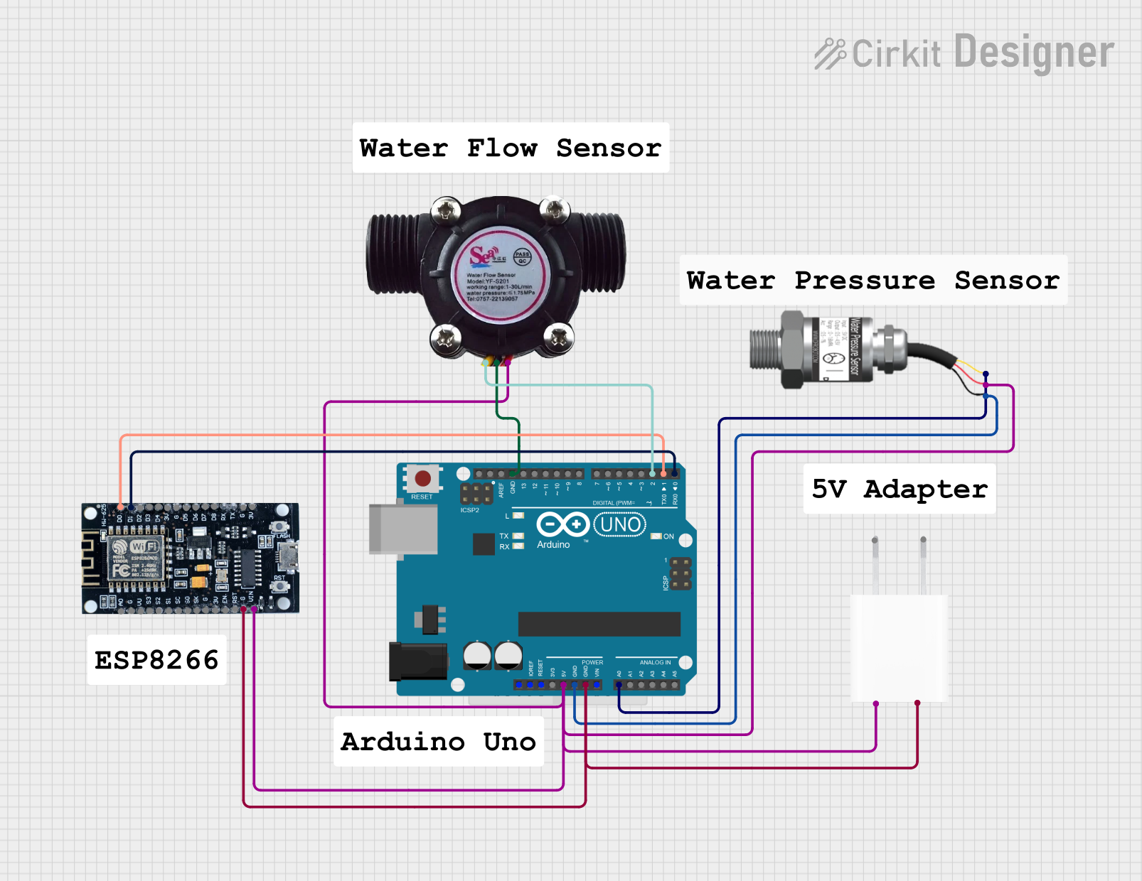
The Water Sensor is a device designed to detect the presence of water or measure moisture levels. It is commonly used in applications such as leak detection, water level monitoring, and soil moisture measurement. The sensor operates by detecting changes in conductivity when water comes into contact with its exposed electrodes. Its simplicity and versatility make it a popular choice for both hobbyist and professional projects.
Explore Projects Built with Water Sensor
Explore Projects Built with Water Sensor
Common Applications
- Leak detection in homes, offices, and industrial settings
- Monitoring water levels in tanks or reservoirs
- Soil moisture measurement for smart irrigation systems
- Flood detection and prevention systems
- Integration with microcontrollers like Arduino for IoT applications
Technical Specifications
Below are the key technical details of a typical water sensor:
| Parameter | Value |
|---|---|
| Operating Voltage | 3.3V - 5V |
| Operating Current | < 20mA |
| Output Type | Analog and Digital |
| Dimensions | ~40mm x 20mm x 8mm |
| Detection Area | Exposed PCB electrodes |
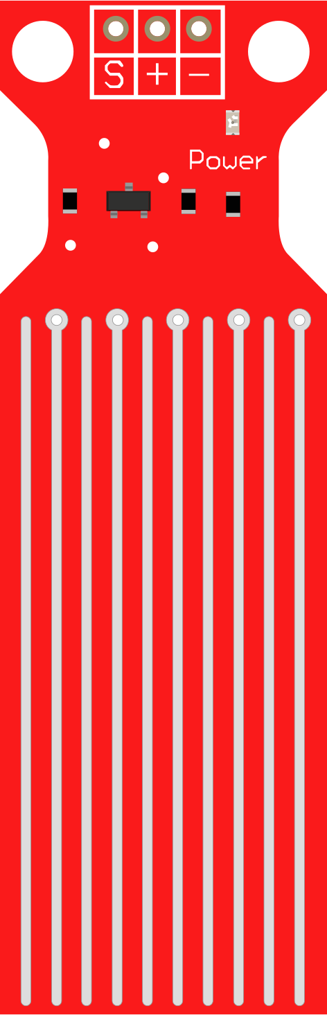
| Interface | 3-pin (VCC, GND, Signal) |
Pin Configuration and Descriptions
The water sensor typically has a 3-pin interface. Below is the pinout description:
| Pin | Name | Description |
|---|---|---|
| 1 | VCC | Power supply pin (3.3V - 5V) |
| 2 | GND | Ground connection |
| 3 | Signal | Outputs an analog or digital signal based on water |
| presence or moisture level |
Usage Instructions
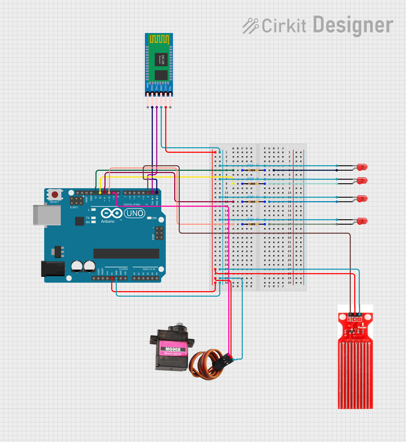
How to Use the Water Sensor in a Circuit
Connect the Sensor:
- Connect the
VCCpin to a 3.3V or 5V power source. - Connect the
GNDpin to the ground of your circuit. - Connect the
Signalpin to an analog or digital input pin of your microcontroller (e.g., Arduino).
- Connect the
Analog vs. Digital Output:
- The analog output provides a voltage proportional to the water or moisture level.
- The digital output is triggered when the water level exceeds a preset threshold (adjustable via an onboard potentiometer, if available).
Example Circuit:
- Use a pull-up resistor if necessary for the digital output.
- Ensure the sensor is placed in the area where water detection is required.
Important Considerations and Best Practices
- Avoid prolonged exposure to water, as it may corrode the sensor's electrodes.
- Use the sensor in low-voltage circuits to prevent damage.
- If using the sensor outdoors, ensure it is protected from environmental factors like dust and extreme temperatures.
- Calibrate the sensor for your specific application, especially when using the analog output.
Example Code for Arduino UNO
Below is an example of how to use the water sensor with an Arduino UNO:
// Water Sensor Example Code for Arduino UNO
// This code reads both analog and digital outputs from the water sensor
// and displays the results in the Serial Monitor.

const int analogPin = A0;  // Analog pin connected to the sensor's Signal pin
const int digitalPin = 2;  // Digital pin connected to the sensor's Signal pin
const int ledPin = 13;     // LED pin to indicate water detection (optional)

void setup() {
  pinMode(digitalPin, INPUT);  // Set digital pin as input
  pinMode(ledPin, OUTPUT);     // Set LED pin as output
  Serial.begin(9600);          // Initialize serial communication
}

void loop() {
  // Read analog value from the sensor
  int analogValue = analogRead(analogPin);
  // Read digital value from the sensor
  int digitalValue = digitalRead(digitalPin);

  // Print the values to the Serial Monitor
  Serial.print("Analog Value: ");
  Serial.print(analogValue);
  Serial.print(" | Digital Value: ");
  Serial.println(digitalValue);

  // Turn on LED if water is detected (digital output is HIGH)
  if (digitalValue == HIGH) {
    digitalWrite(ledPin, HIGH);
  } else {
    digitalWrite(ledPin, LOW);
  }

  delay(500);  // Wait for 500ms before the next reading
}
Troubleshooting and FAQs
Common Issues and Solutions
No Output from the Sensor:
- Ensure the sensor is properly connected to the power supply and ground.
- Verify that the
Signalpin is correctly connected to the microcontroller.
Inconsistent Readings:
- Check for corrosion or dirt on the sensor's electrodes and clean them if necessary.
- Ensure the sensor is not exposed to excessive water for long periods.
Digital Output Not Triggering:
- Adjust the onboard potentiometer (if available) to set the correct threshold.
- Verify that the digital pin on the microcontroller is configured as an input.
Analog Output Not Changing:
- Ensure the sensor is in contact with water or moisture.
- Check the analog pin connection and confirm it is functioning correctly.
FAQs
Q: Can the water sensor be submerged in water?
A: While the sensor can detect water, prolonged submersion may damage the electrodes. It is recommended to use it for short-term detection or in controlled environments.
Q: How do I protect the sensor from corrosion?
A: Apply a protective coating (e.g., conformal coating) to the non-detection areas of the sensor. Avoid coating the exposed electrodes.
Q: Can I use the water sensor with a Raspberry Pi?
A: Yes, the sensor can be used with a Raspberry Pi. Connect the Signal pin to a GPIO pin and use an ADC (Analog-to-Digital Converter) for analog readings.
Q: What is the maximum distance between the sensor and the microcontroller?
A: The distance depends on the quality of the wires and the environment. For best results, keep the distance under 1 meter to avoid signal degradation.