How to Use 1.54" 200×200px e-paper SSD1681: Examples, Pinouts, and Specs
Documentation for 1.54" 200×200px E-Paper Display with SSD1681 Driver IC
1. Introduction
The 1.54" 200×200px E-Paper Display powered by the SSD1681 driver IC is a low-power display module designed for applications requiring high-resolution graphics and minimal energy consumption. E-paper technology mimics the appearance of ink on paper, making it ideal for devices that need to display static or semi-static content for extended periods without consuming significant power.
This display is particularly well-suited for battery-operated devices, such as:
- E-readers and portable displays
- Smart tags and price labels
- Wearable devices
- IoT dashboards
- Electronic shelf labels (ESL)
The SSD1681 driver IC enables precise control of the display, supporting partial updates and grayscale rendering. Its low power consumption makes it an excellent choice for energy-efficient designs.
2. Technical Specifications
2.1 Key Technical Details
| Parameter | Value |
|---|---|
| Display Type | E-Paper (Electronic Ink) |
| Resolution | 200 × 200 pixels |
| Display Size | 1.54 inches (diagonal) |
| Driver IC | SSD1681 |
| Interface | SPI (Serial Peripheral Interface) |
| Operating Voltage | 3.3V |
| Logic Voltage | 3.3V |
| Power Consumption | ~0.5mW (during refresh) |
| Standby Current | < 1µA |
| Refresh Time | ~2 seconds (full refresh) |
| Grayscale Support | 2-level (black and white) |
| Operating Temperature | -20°C to 70°C |
| Storage Temperature | -25°C to 80°C |
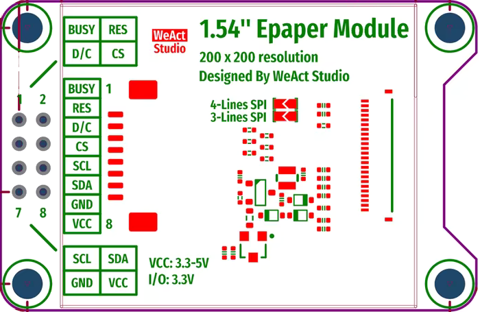
2.2 Pin Configuration and Descriptions
| Pin Name | Pin Number | Description |
|---|---|---|
| VCC | 1 | Power supply input (3.3V). |
| GND | 2 | Ground connection. |
| DIN | 3 | SPI data input (MOSI). |
| CLK | 4 | SPI clock input (SCK). |
| CS | 5 | Chip select (active low). |
| DC | 6 | Data/Command control pin. High for data, low for command. |
| RST | 7 | Reset pin. Active low. |
| BUSY | 8 | Busy status output. High when the display is busy refreshing. |
3. Usage Instructions
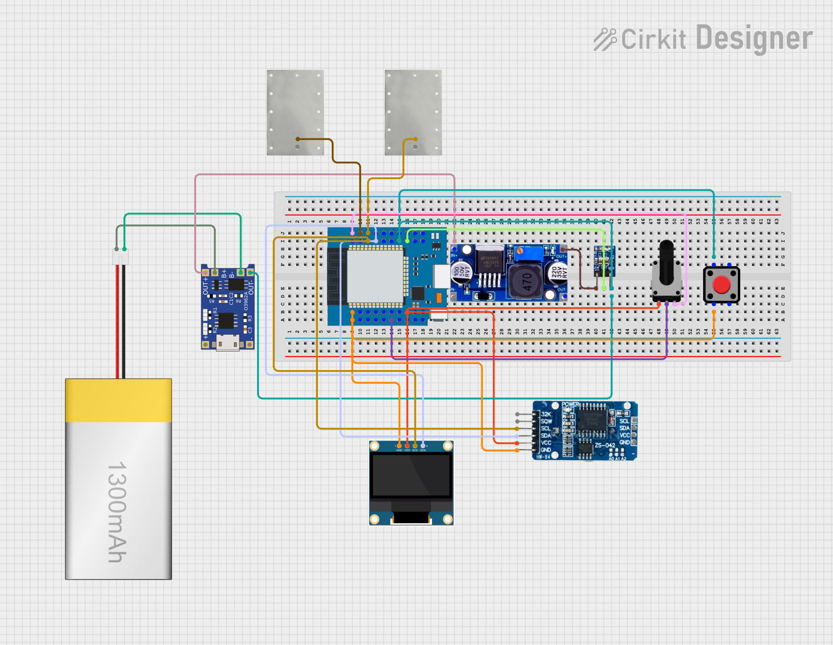
3.1 Connecting the Display to an Arduino UNO
To use the 1.54" e-paper display with an Arduino UNO, connect the pins as follows:
| E-Paper Pin | Arduino UNO Pin |
|---|---|
| VCC | 3.3V |
| GND | GND |
| DIN | D11 (MOSI) |
| CLK | D13 (SCK) |
| CS | D10 |
| DC | D9 |
| RST | D8 |
| BUSY | D7 |
3.2 Example Code for Arduino UNO
Below is an example Arduino sketch to initialize the display and render a simple "Hello, World!" message. This code uses the GxEPD library, a popular library for e-paper displays.
#include <GxEPD.h>          // Include the GxEPD library for e-paper displays
#include <GxGDEH0154D67.h>  // Include the specific driver for the 1.54" display
#include <Adafruit_GFX.h>   // Include Adafruit GFX library for graphics support

// Define the connections for the e-paper display
#define CS_PIN 10   // Chip select pin
#define DC_PIN 9    // Data/Command pin
#define RST_PIN 8   // Reset pin
#define BUSY_PIN 7  // Busy pin

// Initialize the display object
GxIO_Class io(SPI, CS_PIN, DC_PIN, RST_PIN);
GxEPD_Class display(io, RST_PIN, BUSY_PIN);

void setup() {
  // Initialize serial communication for debugging
  Serial.begin(9600);
  Serial.println("Initializing e-paper display...");

  // Initialize the e-paper display
  display.init();
  display.setRotation(0);  // Set rotation (0, 1, 2, or 3)

  // Clear the display
  display.fillScreen(GxEPD_WHITE);
  display.update();

  // Display "Hello, World!" message
  display.setTextColor(GxEPD_BLACK);
  display.setCursor(20, 50);  // Set cursor position (x, y)
  display.setTextSize(2);     // Set text size
  display.print("Hello, World!");
  display.update();           // Refresh the display
}

void loop() {
  // Nothing to do in the loop
}
3.3 Important Considerations
- Power Supply: Ensure the display is powered with a stable 3.3V source. Using 5V may damage the module.
- Refresh Time: The display requires ~2 seconds for a full refresh. Avoid frequent updates to conserve power.
- Partial Updates: The SSD1681 supports partial updates, which are faster and consume less power. Use this feature for dynamic content.
- Avoid Ghosting: Perform a full refresh periodically to prevent ghosting artifacts on the display.
4. Troubleshooting and FAQs
4.1 Common Issues and Solutions
| Issue | Possible Cause | Solution |
|---|---|---|
| Display does not turn on | Incorrect wiring or insufficient power | Verify all connections and ensure a stable 3.3V power supply. |
| Display shows no content | Incorrect SPI communication | Check SPI connections and ensure the correct pins are defined in the code. |
| Display refresh is slow | Full refresh mode is being used | Use partial updates for faster refresh rates. |
| Ghosting artifacts on the screen | Lack of periodic full refresh | Perform a full refresh periodically to clear ghosting. |
| BUSY pin remains high indefinitely | Display is stuck in a busy state | Reset the display by toggling the RST pin. |
4.2 Frequently Asked Questions
Can I use this display with a 5V microcontroller?
No, the display operates at 3.3V. Use a level shifter if your microcontroller operates at 5V.How do I reduce power consumption?
Minimize the number of refreshes and use partial updates whenever possible. Ensure the display enters standby mode when not in use.Can I display grayscale images?
No, this display supports only 2-level grayscale (black and white).What libraries are compatible with this display?
The GxEPD library is highly recommended for Arduino. It supports the SSD1681 driver IC and provides easy-to-use functions.
5. Conclusion
The 1.54" 200×200px E-Paper Display with SSD1681 Driver IC is a versatile and energy-efficient solution for a wide range of applications. Its low power consumption, high resolution, and paper-like appearance make it ideal for battery-powered devices and static content displays. By following the guidelines and best practices outlined in this documentation, you can seamlessly integrate this display into your projects and achieve optimal performance.
Explore Projects Built with 1.54" 200×200px e-paper SSD1681


Explore Projects Built with 1.54" 200×200px e-paper SSD1681