How to Use Módulo de medición de 3,7-4,2 V: Examples, Pinouts, and Specs
Introduction
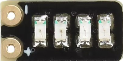
The Módulo de medición de 3,7-4,2 V is a compact and efficient voltage measurement module designed to accurately measure and display voltages within the range of 3.7 to 4.2 volts. This module is commonly used in battery management systems, particularly for lithium-ion batteries, to monitor their charge levels and ensure safe operation. Its simplicity and reliability make it a popular choice for applications requiring precise voltage monitoring.
Explore Projects Built with Módulo de medición de 3,7-4,2 V
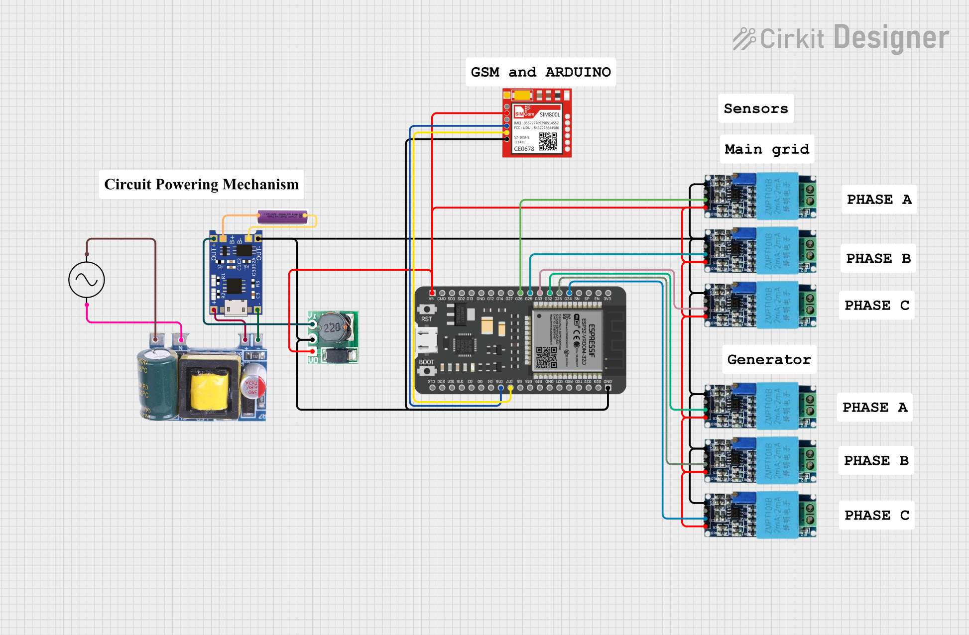


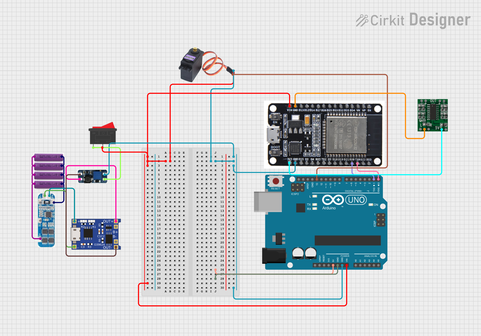
Explore Projects Built with Módulo de medición de 3,7-4,2 V
Common Applications and Use Cases
- Lithium-ion battery monitoring in portable devices
- Battery management systems (BMS) for electric vehicles
- DIY electronics projects involving rechargeable batteries
- Voltage monitoring in power banks and solar charging systems
Technical Specifications
The following table outlines the key technical details of the Módulo de medición de 3,7-4,2 V:
| Parameter | Specification |
|---|---|
| Operating Voltage Range | 3.7 V to 4.2 V |
| Measurement Accuracy | ±0.1 V |
| Input Voltage Tolerance | Up to 5 V |
| Display Type | 7-segment LED or LCD (varies by model) |
| Power Consumption | < 10 mA |
| Operating Temperature | -10°C to 60°C |
| Dimensions | 30 mm x 15 mm x 10 mm |
Pin Configuration and Descriptions
The module typically has three pins for easy integration into circuits. The pin configuration is as follows:
| Pin | Name | Description |
|---|---|---|
| 1 | VCC | Positive power supply input (3.7 V to 4.2 V) |
| 2 | GND | Ground connection |
| 3 | OUT | Voltage measurement output (analog or digital signal) |
Usage Instructions
How to Use the Component in a Circuit
- Power the Module: Connect the VCC pin to the positive terminal of the battery or power source (3.7 V to 4.2 V). Connect the GND pin to the negative terminal.
- Voltage Measurement: The module will automatically measure the input voltage and display it on the built-in display (if available). Alternatively, the OUT pin can be connected to a microcontroller (e.g., Arduino) to read the voltage digitally or as an analog signal.
- Integration with Microcontrollers: If using the OUT pin, connect it to an analog input pin on your microcontroller for further processing or display.
Important Considerations and Best Practices
- Ensure the input voltage does not exceed the module's maximum tolerance of 5 V to avoid damage.
- Use proper connections to avoid loose wires, which can lead to inaccurate readings.
- If the module includes a display, ensure it is visible and not obstructed by other components.
- For long-term use, consider adding a capacitor across the VCC and GND pins to stabilize the power supply.
Example: Connecting to an Arduino UNO
The following example demonstrates how to connect the module to an Arduino UNO and read the voltage using the analog input pin.
Circuit Diagram
- Connect the module's VCC pin to the positive terminal of the battery.
- Connect the GND pin to the Arduino's GND.
- Connect the OUT pin to the Arduino's A0 pin.
Arduino Code
// Define the analog pin connected to the module's OUT pin
const int voltagePin = A0;

// Define the reference voltage of the Arduino (5V for most boards)
const float referenceVoltage = 5.0;

// Define the maximum ADC resolution (10-bit ADC = 1024 levels)
const int adcResolution = 1024;

void setup() {
  // Initialize serial communication for debugging
  Serial.begin(9600);
}

void loop() {
  // Read the analog value from the module
  int analogValue = analogRead(voltagePin);

  // Convert the analog value to a voltage
  float measuredVoltage = (analogValue * referenceVoltage) / adcResolution;

  // Print the measured voltage to the Serial Monitor
  Serial.print("Measured Voltage: ");
  Serial.print(measuredVoltage);
  Serial.println(" V");

  // Add a delay for stability
  delay(1000);
}
Troubleshooting and FAQs
Common Issues and Solutions
No Display or Incorrect Readings
- Cause: Loose or incorrect connections.
- Solution: Double-check all connections, ensuring VCC and GND are properly connected.
Module Overheating
- Cause: Input voltage exceeds the maximum tolerance of 5 V.
- Solution: Verify the input voltage and ensure it is within the specified range.
Fluctuating Readings
- Cause: Unstable power supply or noise in the circuit.
- Solution: Add a capacitor (e.g., 10 µF) across the VCC and GND pins to stabilize the power supply.
Arduino Reads Incorrect Voltage
- Cause: Incorrect reference voltage or calibration.
- Solution: Ensure the Arduino's reference voltage matches the actual supply voltage. Adjust the code if necessary.
FAQs
Q: Can this module measure voltages outside the 3.7-4.2 V range?
A: No, the module is specifically designed for this range. Using it outside this range may result in inaccurate readings or damage.
Q: Is the module compatible with 3.3 V microcontrollers?
A: Yes, but ensure the OUT pin's output voltage is within the microcontroller's input range.
Q: Can I use this module for continuous monitoring?
A: Yes, the module is suitable for continuous monitoring, provided the input voltage remains within the specified range.