Cirkit Designer Logo
Cirkit Designer
Your all-in-one circuit design IDE
Home / 
Component Documentation

How to Use Controllino MEGA: Examples, Pinouts, and Specs

Image of Controllino MEGA
Cirkit Designer LogoDesign with Controllino MEGA in Cirkit Designer

Introduction

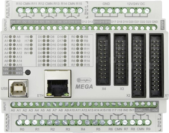
The Controllino MEGA is a robust Programmable Logic Controller (PLC) that leverages the Arduino MEGA platform's flexibility and ease of use. It is tailored for industrial applications, providing a reliable solution for automation and control systems. The Controllino MEGA is suitable for a variety of applications, including but not limited to, machine control, building automation, and process control.

Explore Projects Built with Controllino MEGA

Use Cirkit Designer to design, explore, and prototype these projects online. Some projects support real-time simulation. Click "Open Project" to start designing instantly!
Arduino Mega 2560 Controlled Robotic Vehicle with Bluetooth Interface and MPU-6050 Sensor Integration
Image of BalancingRobot-V2: A project utilizing Controllino MEGA in a practical application
This is a robotic control circuit featuring an Arduino Mega 2560 microcontroller, which manages two DC motors via an L298N motor driver for motion control. It includes an MPU-6050 sensor for motion tracking and an HC-06 Bluetooth module for wireless communication. The Domino-8 connector facilitates power and signal connections among the components.
Cirkit Designer LogoOpen Project in Cirkit Designer
Arduino Mega 2560-Controlled Servo System with Bluetooth and Sensor Interface
Image of Završni: A project utilizing Controllino MEGA in a practical application
This is a microcontroller-based control system featuring an Arduino Mega 2560, designed to receive inputs from a rotary potentiometer, push switches, and an IR sensor, and to drive multiple servos and an LCD display. It includes an HC-05 Bluetooth module for wireless communication, allowing for remote interfacing and control.
Cirkit Designer LogoOpen Project in Cirkit Designer
Arduino Mega 2560 Controlled Robotic Vehicle with Joystick and Ultrasonic Sensor
Image of aa: A project utilizing Controllino MEGA in a practical application
This is an interactive control circuit based on the Arduino Mega 2560, designed to manipulate two DC motors with an Arduino Motor Shield, respond to analog joystick movements, measure distances with an ultrasonic sensor, and provide visual feedback through a red LED. User inputs can be registered through a pushbutton, and the circuit is prepped for further development with a basic code structure in place.
Cirkit Designer LogoOpen Project in Cirkit Designer
Arduino Mega 2560 Controlled Robotic System with Battery Power and Motor Drivers
Image of Circuit diagram : A project utilizing Controllino MEGA in a practical application
This circuit is a motor control system powered by a 12V battery, featuring an Arduino Mega 2560 microcontroller that controls multiple 775 motors through two H-bridge motor drivers. The power distribution board manages the power supply, with fuses and a rocker switch for safety and control.
Cirkit Designer LogoOpen Project in Cirkit Designer

Explore Projects Built with Controllino MEGA

Use Cirkit Designer to design, explore, and prototype these projects online. Some projects support real-time simulation. Click "Open Project" to start designing instantly!
Image of BalancingRobot-V2: A project utilizing Controllino MEGA in a practical application
Arduino Mega 2560 Controlled Robotic Vehicle with Bluetooth Interface and MPU-6050 Sensor Integration
This is a robotic control circuit featuring an Arduino Mega 2560 microcontroller, which manages two DC motors via an L298N motor driver for motion control. It includes an MPU-6050 sensor for motion tracking and an HC-06 Bluetooth module for wireless communication. The Domino-8 connector facilitates power and signal connections among the components.
Cirkit Designer LogoOpen Project in Cirkit Designer
Image of Završni: A project utilizing Controllino MEGA in a practical application
Arduino Mega 2560-Controlled Servo System with Bluetooth and Sensor Interface
This is a microcontroller-based control system featuring an Arduino Mega 2560, designed to receive inputs from a rotary potentiometer, push switches, and an IR sensor, and to drive multiple servos and an LCD display. It includes an HC-05 Bluetooth module for wireless communication, allowing for remote interfacing and control.
Cirkit Designer LogoOpen Project in Cirkit Designer
Image of aa: A project utilizing Controllino MEGA in a practical application
Arduino Mega 2560 Controlled Robotic Vehicle with Joystick and Ultrasonic Sensor
This is an interactive control circuit based on the Arduino Mega 2560, designed to manipulate two DC motors with an Arduino Motor Shield, respond to analog joystick movements, measure distances with an ultrasonic sensor, and provide visual feedback through a red LED. User inputs can be registered through a pushbutton, and the circuit is prepped for further development with a basic code structure in place.
Cirkit Designer LogoOpen Project in Cirkit Designer
Image of Circuit diagram : A project utilizing Controllino MEGA in a practical application
Arduino Mega 2560 Controlled Robotic System with Battery Power and Motor Drivers
This circuit is a motor control system powered by a 12V battery, featuring an Arduino Mega 2560 microcontroller that controls multiple 775 motors through two H-bridge motor drivers. The power distribution board manages the power supply, with fuses and a rocker switch for safety and control.
Cirkit Designer LogoOpen Project in Cirkit Designer

Technical Specifications

General Features

  • Microcontroller: ATmega2560
  • Clock Speed: 16 MHz
  • Flash Memory: 256 KB
  • SRAM: 8 KB
  • EEPROM: 4 KB

Input/Output Specifications

Pin Type Quantity Voltage Range Current Rating Special Features
Digital Inputs 12 5 - 24V DC N/A Opto-isolated
Analog Inputs 6 0 - 10V DC N/A
Digital Outputs 10 5 - 12V DC Up to 2A Half are relay outputs
Relay Outputs 8 250V AC/30V DC Up to 6A SPDT
PWM Outputs 2 5 - 12V DC Up to 2A

Communication Interfaces

  • Serial: RS232, RS485
  • SPI
  • I2C
  • USB

Power Supply

  • Input Voltage: 12 - 24V DC
  • Power Consumption: Varies with usage, typically <10W

Physical Characteristics

  • Dimensions: 119.38 x 115.57 x 77.47 mm
  • Weight: 250g
  • Operating Temperature: -20°C to 55°C

Manufacturer Information

  • Manufacturer: Controllino
  • Part ID: 851123

Usage Instructions

Integration into a Circuit

To integrate the Controllino MEGA into a circuit, follow these steps:

  1. Power Supply: Connect a 12 - 24V DC power source to the designated power terminals.
  2. Inputs/Outputs: Connect your sensors, actuators, or other devices to the appropriate I/O terminals, respecting the voltage and current ratings.
  3. Communication: Utilize the RS232, RS485, SPI, I2C, or USB interfaces for communication with other devices or a computer.
  4. Programming: Program the Controllino MEGA using the Arduino IDE or other compatible software platforms.

Best Practices

  • Always ensure that the power supply is disconnected before making any connections to the Controllino MEGA.
  • Use proper wire gauges for the current ratings of the outputs.
  • When dealing with high voltages or currents, follow appropriate safety standards and regulations.
  • Ensure that all connections are secure to prevent accidental disconnections or shorts.

Example Code for Arduino UNO

Here is an example code snippet for controlling a relay on the Controllino MEGA using an Arduino UNO:

// Define the relay pin
const int relayPin = 22; // Controllino MEGA relay pin R1

void setup() {
  // Set the relay pin as an output
  pinMode(relayPin, OUTPUT);
}

void loop() {
  // Turn the relay on
  digitalWrite(relayPin, HIGH);
  delay(1000); // Wait for 1 second
  // Turn the relay off
  digitalWrite(relayPin, LOW);
  delay(1000); // Wait for 1 second
}

Remember to adjust the relayPin variable to match the actual pin number used on the Controllino MEGA.

Troubleshooting and FAQs

Common Issues

  • Power LED is not on: Ensure that the power supply is connected and switched on. Check the voltage with a multimeter.
  • Inputs/Outputs not responding: Verify that the wiring is correct and secure. Check the code for proper pin assignments.
  • Communication failure: Ensure that the correct communication protocol and settings are used. Check the physical connections.

FAQs

Q: Can the Controllino MEGA be programmed with the Arduino IDE? A: Yes, the Controllino MEGA can be programmed with the Arduino IDE, using the same process as for an Arduino MEGA.

Q: What is the maximum current the relay outputs can handle? A: The relay outputs can handle up to 6A for AC loads and up to 10A for DC loads.

Q: Is the Controllino MEGA compatible with Arduino shields? A: While the Controllino MEGA shares similarities with the Arduino MEGA, compatibility with Arduino shields is not guaranteed due to its industrial design and terminal connections.

For further assistance, consult the Controllino MEGA's official documentation or contact Controllino's technical support.