Cirkit Designer Logo
Cirkit Designer
Your all-in-one circuit design IDE
Home / 
Component Documentation

How to Use GPS NEO-6M V2: Examples, Pinouts, and Specs

Image of GPS NEO-6M V2
Cirkit Designer LogoDesign with GPS NEO-6M V2 in Cirkit Designer

Introduction

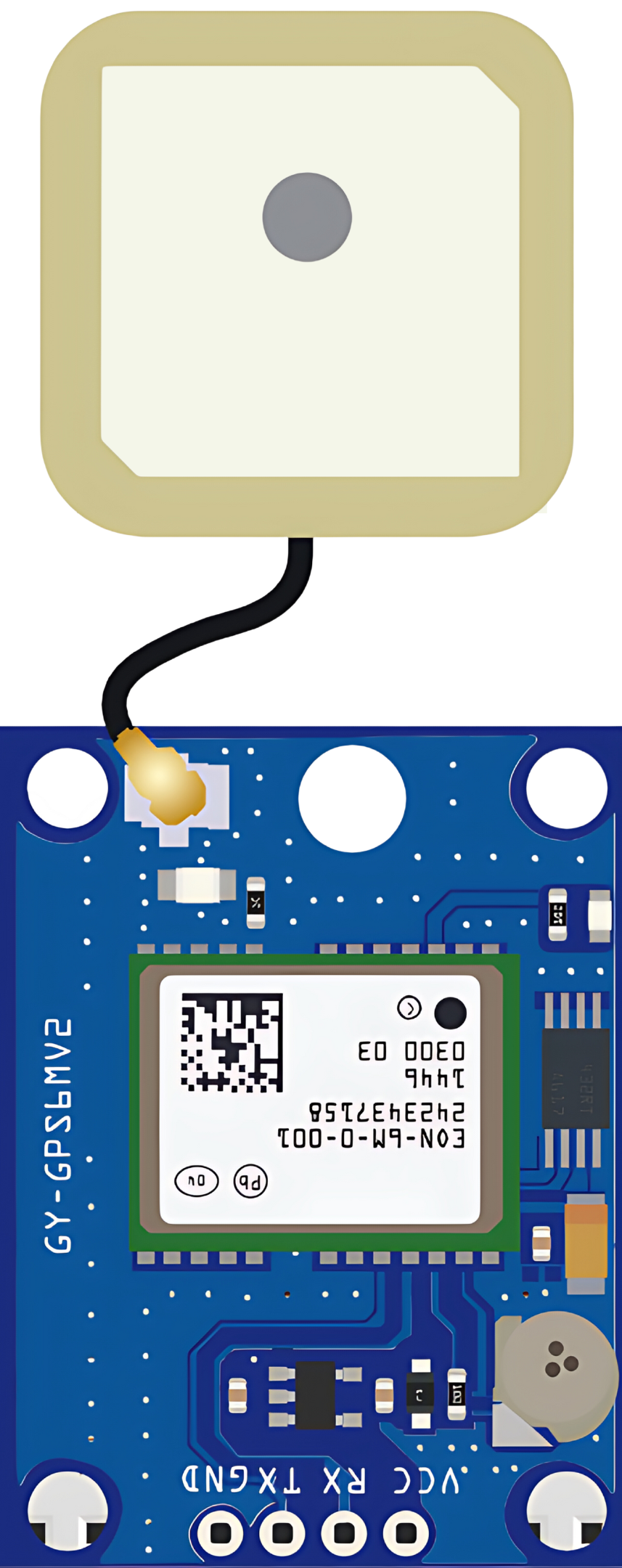
The GPS NEO-6M V2 module is a versatile and compact GPS receiver that offers high-performance satellite navigation by leveraging signals from multiple satellite constellations. It is widely used in a range of applications, including personal navigation systems, asset tracking, drones, and Internet of Things (IoT) devices. The module's ability to provide accurate positioning and speed information makes it an essential component in modern electronics where location-based services are required.

Explore Projects Built with GPS NEO-6M V2

Use Cirkit Designer to design, explore, and prototype these projects online. Some projects support real-time simulation. Click "Open Project" to start designing instantly!
ESP32-Based GPS Tracker with OLED Display and Firebase Integration
Image of ecs: A project utilizing GPS NEO-6M V2 in a practical application
This circuit is a GPS tracking system that uses an ESP32 microcontroller to read location data from a NEO-6M GPS module and display information on a 0.96" OLED screen. The system is powered by a 2000mAh battery with a lithium-ion charger, and it uploads the GPS data to Firebase via WiFi. Additional components include an MPU6050 accelerometer/gyroscope for motion sensing and a buzzer for alerts.
Cirkit Designer LogoOpen Project in Cirkit Designer
ESP32-Based GPS Tracker with OLED Display and Telegram Integration
Image of Yoon: A project utilizing GPS NEO-6M V2 in a practical application
This circuit is a GPS-based tracking system that uses an ESP32 microcontroller to receive GPS data from a NEO 6M module and display the coordinates on a 1.3" OLED screen. It also features WiFi connectivity to send location updates to a remote server, potentially for applications such as asset tracking or navigation assistance.
Cirkit Designer LogoOpen Project in Cirkit Designer
STM32F4-Based Multi-Sensor GPS Tracking System
Image of Phase 1 fc: A project utilizing GPS NEO-6M V2 in a practical application
This circuit integrates an STM32F4 microcontroller with a GPS module (NEO 6M), an accelerometer and gyroscope (MPU-6050), a barometric pressure sensor (BMP280), and a compass (HMC5883L). The microcontroller communicates with the sensors via I2C and the GPS module via UART, enabling it to gather and process environmental and positional data.
Cirkit Designer LogoOpen Project in Cirkit Designer
Arduino UNO-Based GPS and GSM-Enabled Vibration Sensor System with Motor Control
Image of gps based accident detection and alert system: A project utilizing GPS NEO-6M V2 in a practical application
This circuit is a GPS-based tracking system with vibration detection and motor control capabilities. It uses an Arduino UNO to interface with a Neo 6M GPS module for location data, a Sim800l module for GSM communication, an ADXL345 accelerometer for motion sensing, and an SW-420 vibration sensor to detect vibrations. The system also includes a motor driver to control two DC motors and a buzzer for alerts, all powered by a 5V battery.
Cirkit Designer LogoOpen Project in Cirkit Designer

Explore Projects Built with GPS NEO-6M V2

Use Cirkit Designer to design, explore, and prototype these projects online. Some projects support real-time simulation. Click "Open Project" to start designing instantly!
Image of ecs: A project utilizing GPS NEO-6M V2 in a practical application
ESP32-Based GPS Tracker with OLED Display and Firebase Integration
This circuit is a GPS tracking system that uses an ESP32 microcontroller to read location data from a NEO-6M GPS module and display information on a 0.96" OLED screen. The system is powered by a 2000mAh battery with a lithium-ion charger, and it uploads the GPS data to Firebase via WiFi. Additional components include an MPU6050 accelerometer/gyroscope for motion sensing and a buzzer for alerts.
Cirkit Designer LogoOpen Project in Cirkit Designer
Image of Yoon: A project utilizing GPS NEO-6M V2 in a practical application
ESP32-Based GPS Tracker with OLED Display and Telegram Integration
This circuit is a GPS-based tracking system that uses an ESP32 microcontroller to receive GPS data from a NEO 6M module and display the coordinates on a 1.3" OLED screen. It also features WiFi connectivity to send location updates to a remote server, potentially for applications such as asset tracking or navigation assistance.
Cirkit Designer LogoOpen Project in Cirkit Designer
Image of Phase 1 fc: A project utilizing GPS NEO-6M V2 in a practical application
STM32F4-Based Multi-Sensor GPS Tracking System
This circuit integrates an STM32F4 microcontroller with a GPS module (NEO 6M), an accelerometer and gyroscope (MPU-6050), a barometric pressure sensor (BMP280), and a compass (HMC5883L). The microcontroller communicates with the sensors via I2C and the GPS module via UART, enabling it to gather and process environmental and positional data.
Cirkit Designer LogoOpen Project in Cirkit Designer
Image of gps based accident detection and alert system: A project utilizing GPS NEO-6M V2 in a practical application
Arduino UNO-Based GPS and GSM-Enabled Vibration Sensor System with Motor Control
This circuit is a GPS-based tracking system with vibration detection and motor control capabilities. It uses an Arduino UNO to interface with a Neo 6M GPS module for location data, a Sim800l module for GSM communication, an ADXL345 accelerometer for motion sensing, and an SW-420 vibration sensor to detect vibrations. The system also includes a motor driver to control two DC motors and a buzzer for alerts, all powered by a 5V battery.
Cirkit Designer LogoOpen Project in Cirkit Designer

Common Applications and Use Cases

  • Personal and vehicle navigation systems
  • Geocaching and outdoor sports
  • Fleet management and asset tracking
  • Time synchronization for networks
  • Autonomous drones and robotics
  • IoT devices with location-based services

Technical Specifications

Key Technical Details

  • Receiver Type: 50 Channels, GPS L1 frequency, C/A Code
  • Sensitivity: Tracking & Navigation: -161 dBm
  • Time-To-First-Fix: Cold starts: 27s (typ.), Hot starts: 1s (typ.)
  • Accuracy: Position 2.5m CEP
  • Update Rate: Up to 5Hz
  • Operating Voltage: 3.3V-5V
  • Power Consumption: 50mA (typical)

Pin Configuration and Descriptions

Pin Number Name Description
1 VCC Power supply input (3.3V-5V)
2 GND Ground connection
3 TX Transmit data out (TTL level)
4 RX Receive data in (TTL level)
5 PPS Pulse per second output

Usage Instructions

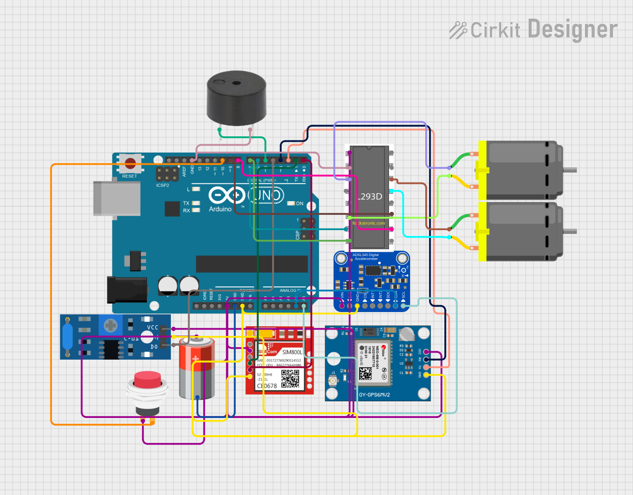
How to Use the Component in a Circuit

  1. Power Supply: Connect the VCC pin to a 3.3V-5V power source and the GND pin to the ground.
  2. Data Communication: Connect the TX pin of the GPS module to the RX pin of the microcontroller and the RX pin to the TX pin of the microcontroller.
  3. Antenna: Ensure the GPS module's antenna has a clear view of the sky for optimal performance.
  4. Serial Interface: Configure the microcontroller's serial interface to the same baud rate as the GPS module (usually 9600 bps).

Important Considerations and Best Practices

  • Antenna Placement: The antenna should have a clear view of the sky. Avoid placing it next to large metal objects or under a roof.
  • Power Supply: Ensure a stable power supply. Voltage fluctuations can cause the module to reset or malfunction.
  • Serial Communication: Use a level shifter if the microcontroller operates at a different logic level than the GPS module.
  • Warm-Up Time: Allow the module a few minutes to warm up and acquire satellite signals upon initial power-up.

Example Code for Arduino UNO

#include <SoftwareSerial.h>

// Create a software serial port called "gpsSerial" on pins 3 (RX) and 4 (TX)
SoftwareSerial gpsSerial(3, 4);

void setup() {
  // Start the Arduino hardware serial port at 9600 baud
  Serial.begin(9600);
  // Start the software serial port at 9600 baud
  gpsSerial.begin(9600);
}

void loop() {
  // Check if data is available on the GPS serial port
  if (gpsSerial.available()) {
    // Forward any available GPS data to the hardware serial port
    Serial.write(gpsSerial.read());
  }
  // Check if data is available on the hardware serial port
  if (Serial.available()) {
    // Forward any available data from the hardware serial port to the GPS
    gpsSerial.write(Serial.read());
  }
}

Troubleshooting and FAQs

Common Issues Users Might Face

  • No Data Output: Ensure the antenna has a clear view of the sky and the module has had sufficient time to acquire satellites.
  • Garbled Data: Check the baud rate settings on both the GPS module and the microcontroller. They must match.
  • Inaccurate Position: Wait for the module to get a stable fix; moving the antenna to a location with a better view of the sky can help.

Solutions and Tips for Troubleshooting

  • Power Cycle: If the module is unresponsive, try power cycling it by disconnecting and reconnecting the power.
  • Check Connections: Verify all connections, especially the serial communication lines, for proper contact and orientation.
  • External Antenna: If the signal is weak, consider using an external antenna with a clear view of the sky.

FAQs

Q: How long does it take for the GPS module to get a fix? A: It typically takes 27 seconds for a cold start and 1 second for a hot start, but this can vary based on environmental conditions.

Q: Can I use the GPS module indoors? A: GPS signals are weak indoors. It's recommended to use the module outdoors or near a window for better signal reception.

Q: What is the PPS pin for? A: The PPS (Pulse Per Second) pin outputs a pulse once per second, which can be used for precise timekeeping or to synchronize multiple GPS receivers.