How to Use SparkFun GPS Breakout: Examples, Pinouts, and Specs
Introduction
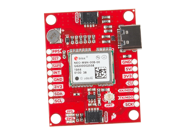
The SparkFun GPS Breakout is a compact and versatile board that provides easy access to GPS functionality. It enables precise location tracking and navigation, making it an essential component for projects involving geolocation, mapping, and time synchronization. The breakout board is designed to interface seamlessly with microcontrollers and other devices, offering a user-friendly way to integrate GPS capabilities into your designs.
Explore Projects Built with SparkFun GPS Breakout

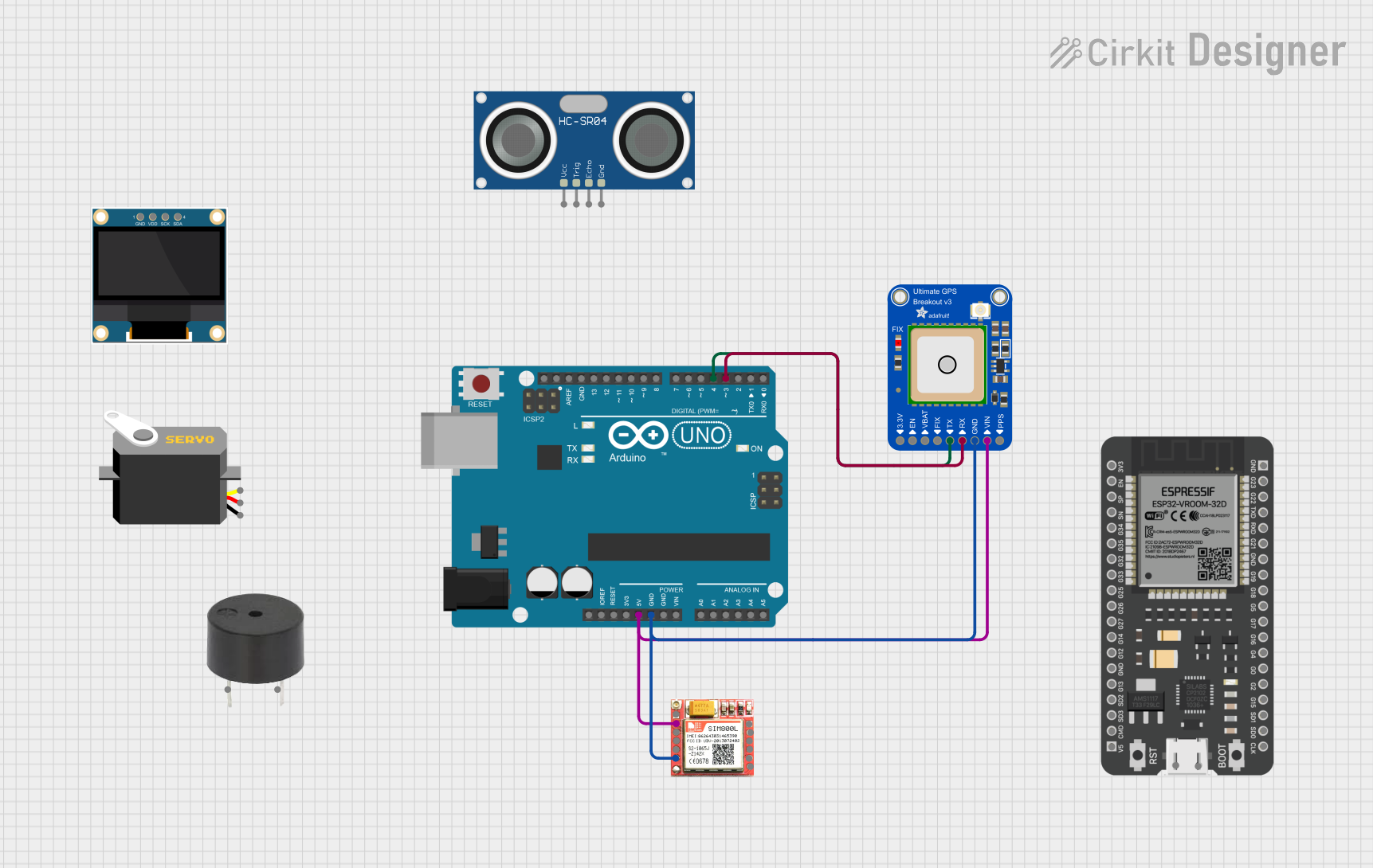
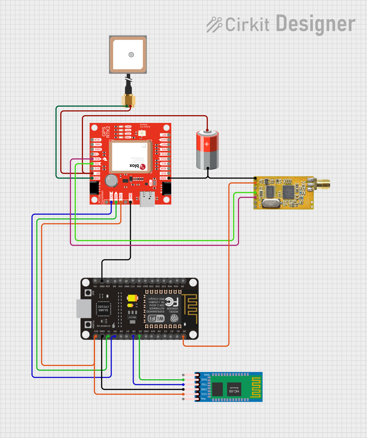

Explore Projects Built with SparkFun GPS Breakout
Common Applications and Use Cases
- Vehicle tracking and navigation systems
- Drones and UAVs for location-based control
- Outdoor robotics and autonomous vehicles
- Geotagging for photography and video
- Time synchronization for IoT devices
- Personal tracking and fitness devices
Technical Specifications
The SparkFun GPS Breakout is built around a high-performance GPS module, offering reliable and accurate location data. Below are the key technical details:
Key Specifications
- Input Voltage: 3.3V to 5.0V
- Communication Protocols: UART (default), I2C
- Baud Rate: 9600 bps (default, configurable)
- Position Accuracy: ±2.5 meters
- Update Rate: Up to 10 Hz
- Antenna: External active antenna (via U.FL connector)
- Operating Temperature: -40°C to +85°C
- Dimensions: 25.4mm x 25.4mm (1" x 1")
Pin Configuration and Descriptions
The SparkFun GPS Breakout features a simple pin layout for easy integration. Below is the pinout table:
| Pin | Name | Description |
|---|---|---|
| 1 | VIN | Power input (3.3V to 5.0V). Supplies power to the GPS module. |
| 2 | GND | Ground connection. |
| 3 | TX | UART Transmit pin. Sends GPS data to the microcontroller. |
| 4 | RX | UART Receive pin. Receives configuration commands from the microcontroller. |
| 5 | SDA | I2C Data line. Used for communication in I2C mode. |
| 6 | SCL | I2C Clock line. Used for communication in I2C mode. |
| 7 | PPS | Pulse Per Second output. Provides a precise timing pulse for synchronization. |
| 8 | GND (Antenna) | Ground connection for the external antenna. |
Usage Instructions
How to Use the Component in a Circuit
- Powering the Module: Connect the VIN pin to a 3.3V or 5.0V power source and the GND pin to ground.
- Connecting to a Microcontroller:
- For UART communication, connect the TX pin of the GPS Breakout to the RX pin of the microcontroller, and the RX pin of the GPS Breakout to the TX pin of the microcontroller.
- For I2C communication, connect the SDA and SCL pins to the corresponding I2C pins on the microcontroller.
- Antenna Connection: Attach an external active antenna to the U.FL connector for optimal GPS signal reception.
- Reading GPS Data: Use a serial monitor or microcontroller code to parse the NMEA sentences output by the GPS module.
Important Considerations and Best Practices
- Antenna Placement: Ensure the external antenna has a clear view of the sky for optimal signal reception.
- Power Supply: Use a stable power source to avoid GPS signal dropouts.
- Baud Rate Configuration: The default baud rate is 9600 bps. If needed, configure the baud rate using appropriate commands.
- PPS Pin: Use the PPS pin for precise timing applications, such as synchronizing clocks in IoT systems.
Example Code for Arduino UNO
Below is an example of how to interface the SparkFun GPS Breakout with an Arduino UNO using UART communication:
#include <SoftwareSerial.h>

// Define RX and TX pins for SoftwareSerial
SoftwareSerial gpsSerial(4, 3); // RX = Pin 4, TX = Pin 3

void setup() {
  Serial.begin(9600); // Start the hardware serial monitor
  gpsSerial.begin(9600); // Start the GPS module at 9600 baud

  Serial.println("SparkFun GPS Breakout Example");
  Serial.println("Waiting for GPS data...");
}

void loop() {
  // Check if data is available from the GPS module
  while (gpsSerial.available()) {
    char c = gpsSerial.read(); // Read a character from the GPS module
    Serial.print(c); // Print the character to the serial monitor

    // Note: The GPS module outputs NMEA sentences, which can be parsed
    // for specific data like latitude, longitude, and time.
  }
}
Troubleshooting and FAQs
Common Issues and Solutions
No GPS Data Output:
- Ensure the GPS module is powered correctly (check VIN and GND connections).
- Verify the TX and RX connections between the GPS Breakout and the microcontroller.
- Check that the baud rate matches the GPS module's default (9600 bps).
Weak or No GPS Signal:
- Ensure the external antenna is connected securely to the U.FL connector.
- Place the antenna in an open area with a clear view of the sky.
- Avoid using the module indoors or near obstructions that block GPS signals.
Incorrect Data Parsing:
- Ensure your code correctly handles NMEA sentences.
- Use a GPS library (e.g., TinyGPS++ for Arduino) to simplify data parsing.
FAQs
Can I use the SparkFun GPS Breakout with 5V logic? Yes, the module is compatible with both 3.3V and 5V logic levels.
What is the default communication protocol? The default protocol is UART, but the module also supports I2C.
How do I change the baud rate? Use configuration commands sent via UART to adjust the baud rate. Refer to the GPS module's datasheet for details.
Can I use the module without an external antenna? While the module may work without an external antenna, using one significantly improves signal reception and accuracy.