How to Use lm2596: Examples, Pinouts, and Specs
Introduction
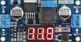
The LM2596 is a step-down (buck) voltage regulator designed to efficiently convert a higher input voltage into a stable, lower output voltage. It is capable of delivering up to 3A of output current, making it ideal for powering a wide range of electronic devices. The LM2596 is widely used in power management applications due to its high efficiency, ease of use, and reliability.
Explore Projects Built with lm2596


Explore Projects Built with lm2596
Common Applications and Use Cases
- Power supply modules for microcontrollers and embedded systems
- Battery-powered devices requiring regulated voltage
- DC-DC converters in industrial and automotive applications
- LED drivers and lighting systems
- Adjustable voltage regulators for prototyping and testing
Technical Specifications
The LM2596 is available in fixed output voltage versions (e.g., 3.3V, 5V, 12V) as well as an adjustable version. Below are the key technical details:
General Specifications
| Parameter | Value |
|---|---|
| Input Voltage Range | 4.5V to 40V |
| Output Voltage Range | 1.23V to 37V (adjustable version) |
| Maximum Output Current | 3A |
| Efficiency | Up to 90% |
| Switching Frequency | 150 kHz |
| Operating Temperature | -40°C to +125°C |
Pin Configuration and Descriptions
The LM2596 is typically available in a 5-pin TO-220 package. Below is the pinout:
| Pin Number | Pin Name | Description |
|---|---|---|
| 1 | VIN | Input voltage pin. Connect to the unregulated DC input voltage. |
| 2 | Output | Regulated output voltage pin. Connect to the load. |
| 3 | Ground | Ground pin. Connect to the system ground. |
| 4 | Feedback | Feedback pin. Used to set the output voltage (adjustable version only). |
| 5 | ON/OFF | Enable pin. Connect to ground to disable the regulator, or leave floating. |
Usage Instructions
How to Use the LM2596 in a Circuit
- Input Voltage: Connect the input voltage (VIN) to the LM2596's input pin. Ensure the input voltage is within the range of 4.5V to 40V.
- Output Voltage: For fixed versions, the output voltage is pre-set (e.g., 5V). For the adjustable version:
- Use a resistor divider network connected to the Feedback pin to set the desired output voltage.
- The output voltage can be calculated using the formula:
[ V_{OUT} = V_{REF} \times \left(1 + \frac{R1}{R2}\right) ]
where ( V_{REF} = 1.23V ), ( R1 ) is the resistor connected between the output and the Feedback pin, and ( R2 ) is the resistor connected between the Feedback pin and ground.
- Capacitors: Add input and output capacitors to stabilize the circuit:
- Input capacitor: 100 µF electrolytic capacitor.
- Output capacitor: 220 µF electrolytic capacitor.
- Inductor: Use an appropriate inductor (e.g., 33 µH) to ensure proper operation and efficiency.
- Enable Pin: If not used, leave the ON/OFF pin floating or connect it to VIN.
Important Considerations and Best Practices
- Heat Dissipation: The LM2596 can generate heat during operation. Use a heatsink if the output current exceeds 2A.
- Ripple Reduction: Use low-ESR capacitors to minimize output voltage ripple.
- PCB Layout: Keep the input and output capacitor connections as close to the regulator as possible to reduce noise.
- Protection: Add a Schottky diode across the input and output to protect against reverse polarity.
Example: Using LM2596 with Arduino UNO
The LM2596 can be used to power an Arduino UNO from a higher voltage source (e.g., a 12V battery). Below is an example circuit and Arduino code:
Circuit Connections
- Connect the 12V input to the VIN pin of the LM2596.
- Set the output voltage to 5V using the adjustable version.
- Connect the 5V output to the Arduino UNO's 5V pin.
Arduino Code
// Example code to blink an LED using Arduino UNO powered by LM2596
const int ledPin = 13; // Pin connected to the onboard LED

void setup() {
  pinMode(ledPin, OUTPUT); // Set the LED pin as an output
}

void loop() {
  digitalWrite(ledPin, HIGH); // Turn the LED on
  delay(1000);               // Wait for 1 second
  digitalWrite(ledPin, LOW);  // Turn the LED off
  delay(1000);               // Wait for 1 second
}
Troubleshooting and FAQs
Common Issues and Solutions
No Output Voltage:
- Check the input voltage. Ensure it is within the specified range (4.5V to 40V).
- Verify the connections, especially the ground and output pins.
- Ensure the ON/OFF pin is not grounded (if used).
Output Voltage is Incorrect:
- For the adjustable version, check the resistor divider network. Ensure the resistor values are correct.
- Verify the feedback pin connection.
Excessive Heat:
- Ensure the output current does not exceed 3A.
- Use a heatsink or improve ventilation around the LM2596.
High Output Ripple:
- Use low-ESR capacitors for input and output.
- Check the inductor value and ensure it matches the recommended specifications.
FAQs
Q: Can the LM2596 be used with a 24V input to power a 5V device?
A: Yes, the LM2596 can step down a 24V input to 5V, provided the output current does not exceed 3A.
Q: What is the efficiency of the LM2596?
A: The efficiency can reach up to 90%, depending on the input voltage, output voltage, and load conditions.
Q: Can I use the LM2596 without an inductor?
A: No, an inductor is essential for the proper operation of the LM2596 as a switching regulator.
Q: How do I calculate the output voltage for the adjustable version?
A: Use the formula ( V_{OUT} = V_{REF} \times \left(1 + \frac{R1}{R2}\right) ), where ( V_{REF} = 1.23V ).
By following this documentation, you can effectively use the LM2596 in your projects and troubleshoot common issues.