
How to Use NEO 6m GPS Module: Examples, Pinouts, and Specs
 Design with NEO 6m GPS Module in Cirkit Designer
Introduction
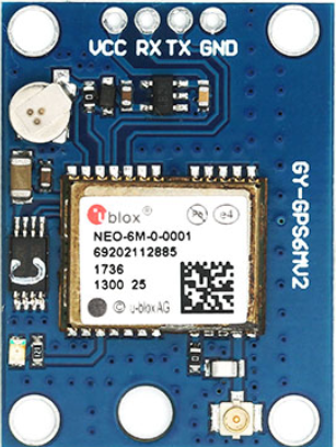
The NEO-6M GPS Module is a compact and highly sensitive GPS receiver designed to provide accurate positioning and timing data. It is widely used in navigation systems, robotics, drones, and IoT applications due to its low power consumption, high sensitivity, and reliable performance. The module integrates a GPS receiver with an onboard ceramic antenna, making it easy to use in a variety of projects requiring location tracking or time synchronization.
Common applications include:
- Vehicle tracking and navigation systems
- Autonomous robots and drones
- IoT devices requiring geolocation
- Outdoor sports and fitness devices
- Timing synchronization in distributed systems
Explore Projects Built with NEO 6m GPS Module
 Open Project in Cirkit Designer
 Open Project in Cirkit Designer
 Open Project in Cirkit Designer
 Open Project in Cirkit Designer
Explore Projects Built with NEO 6m GPS Module
Open Project in Cirkit DesignerOpen Project in Cirkit DesignerOpen Project in Cirkit DesignerOpen Project in Cirkit DesignerTechnical Specifications
The NEO-6M GPS Module is built for versatility and ease of integration. Below are its key technical details:
General Specifications
| Parameter | Value |
|---|---|
| GPS Receiver Type | u-blox NEO-6M |
| Positioning Accuracy | 2.5 meters CEP |
| Sensitivity | -161 dBm |
| Update Rate | 1 Hz (default), up to 5 Hz |
| Communication Protocol | UART, NMEA, UBX |
| Operating Voltage | 3.3V to 5V |
| Power Consumption | ~45 mA |
| Operating Temperature | -40°C to +85°C |
| Dimensions | 25mm x 35mm x 6mm |
Pin Configuration
The NEO-6M GPS Module typically has a 4-pin interface for easy connection. Below is the pinout description:
| Pin Name | Pin Number | Description |
|---|---|---|
| VCC | 1 | Power input (3.3V to 5V) |
| GND | 2 | Ground connection |
| TX | 3 | UART Transmit pin (sends GPS data) |
| RX | 4 | UART Receive pin (receives configuration data) |
Usage Instructions
Connecting the NEO-6M GPS Module
To use the NEO-6M GPS Module in a circuit, follow these steps:
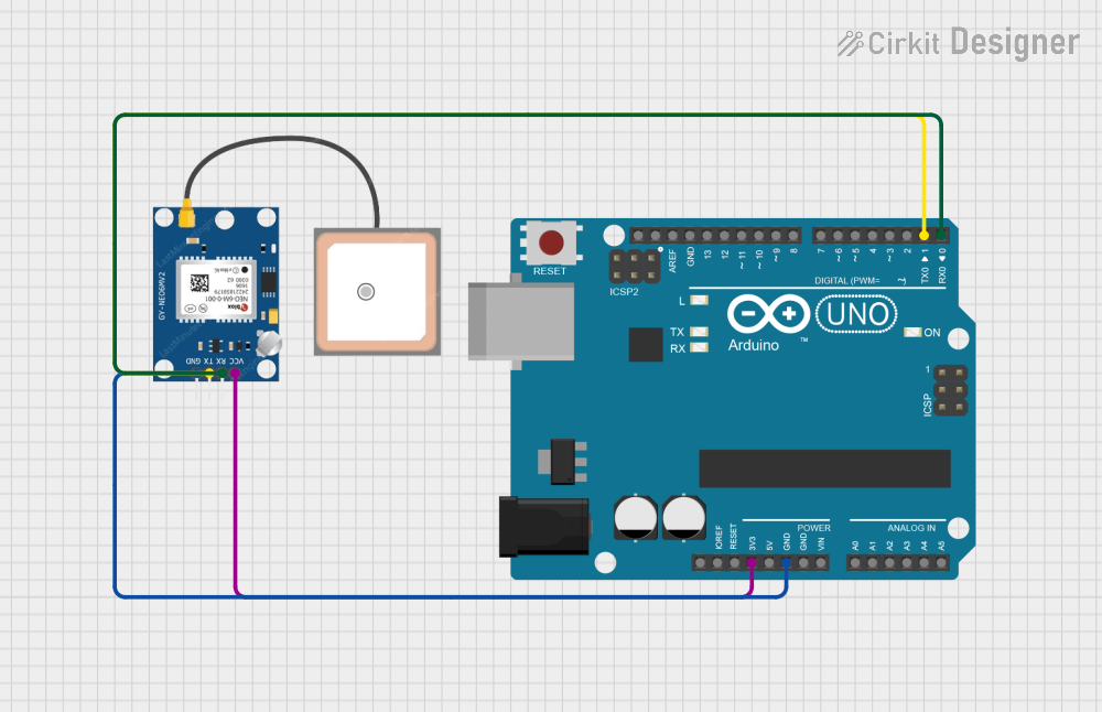
- Power the Module: Connect the
VCCpin to a 3.3V or 5V power source and theGNDpin to ground. - Establish UART Communication: Connect the
TXpin of the module to the RX pin of your microcontroller (e.g., Arduino UNO) and theRXpin of the module to the TX pin of the microcontroller. - Antenna Placement: Ensure the onboard ceramic antenna has a clear view of the sky for optimal GPS signal reception. Avoid placing the module near metal objects or inside enclosures that block signals.
Arduino UNO Example Code
Below is an example of how to interface the NEO-6M GPS Module with an Arduino UNO to read GPS data:
#include <SoftwareSerial.h>

// Define RX and TX pins for SoftwareSerial
SoftwareSerial gpsSerial(4, 3); // RX = Pin 4, TX = Pin 3

void setup() {
  Serial.begin(9600);          // Initialize Serial Monitor at 9600 baud
  gpsSerial.begin(9600);       // Initialize GPS module at 9600 baud
  Serial.println("NEO-6M GPS Module Test");
}

void loop() {
  // Check if data is available from the GPS module
  while (gpsSerial.available()) {
    char gpsData = gpsSerial.read(); // Read one character from GPS module
    Serial.print(gpsData);           // Print the character to Serial Monitor
  }
}
Important Considerations
- Baud Rate: The default baud rate of the NEO-6M GPS Module is 9600. Ensure your microcontroller matches this setting.
- Signal Reception: For best results, use the module outdoors or near a window to ensure a clear line of sight to GPS satellites.
- Power Supply: Use a stable power source to avoid interruptions in GPS data.
Troubleshooting and FAQs
Common Issues and Solutions
No GPS Data Received
- Cause: Poor satellite signal reception.
- Solution: Move the module to an open area with a clear view of the sky.
Garbage Data in Serial Monitor
- Cause: Incorrect baud rate configuration.
- Solution: Ensure both the GPS module and microcontroller are set to the same baud rate (default: 9600).
Module Not Powering On
- Cause: Incorrect power supply voltage.
- Solution: Verify that the
VCCpin is connected to a 3.3V or 5V source.
Intermittent Data Loss
- Cause: Unstable power supply or interference.
- Solution: Use a decoupling capacitor near the module and avoid placing it near high-frequency devices.
FAQs
Q: Can the NEO-6M GPS Module work indoors?
A: While the module may work indoors near windows, its performance is significantly reduced. For reliable operation, use it outdoors with a clear view of the sky.
Q: How long does it take to get a GPS fix?
A: The time to first fix (TTFF) depends on signal conditions. A cold start typically takes 30-60 seconds, while a warm start can take as little as 1-5 seconds.
Q: Can I increase the update rate?
A: Yes, the update rate can be configured up to 5 Hz using UBX commands. However, higher update rates may increase power consumption.
Q: Is an external antenna required?
A: The module includes an onboard ceramic antenna, but an external active antenna can be connected for improved performance in challenging environments.
By following this documentation, you can effectively integrate the NEO-6M GPS Module into your projects and troubleshoot common issues with ease.