How to Use SSRelay: Examples, Pinouts, and Specs
Introduction
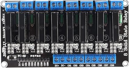
The SSRelay by AITRIP (Manufacturer Part ID: SSRelay) is a Solid State Relay (SSR), an electronic switching device that uses semiconductor components to perform switching operations. Unlike traditional mechanical relays, SSRs offer faster switching speeds, longer operational life, and silent operation due to the absence of moving parts. These features make the SSRelay ideal for applications requiring high reliability and precision.
Explore Projects Built with SSRelay


Explore Projects Built with SSRelay
Common Applications and Use Cases
- Industrial automation and control systems
- Home appliances and smart home devices
- Motor speed control and heating element regulation
- LED lighting systems
- Microcontroller-based projects (e.g., Arduino, Raspberry Pi)
Technical Specifications
Key Technical Details
| Parameter | Value |
|---|---|
| Input Control Voltage | 3V to 32V DC |
| Output Load Voltage | 24V to 380V AC |
| Output Load Current | Up to 2A |
| Trigger Current | 7.5mA (typical) |
| Isolation Voltage | ≥ 2500V AC |
| Switching Speed | ≤ 10ms |
| Operating Temperature | -30°C to +80°C |
| Dimensions | 43mm x 25mm x 23mm |
Pin Configuration and Descriptions
The SSRelay typically has four pins, as described in the table below:
| Pin Number | Name | Description |
|---|---|---|
| 1 | Input+ (Vcc) | Positive terminal for the control signal (3V to 32V DC). |
| 2 | Input- (GND) | Ground terminal for the control signal. |
| 3 | Output+ | Positive terminal for the AC load. |
| 4 | Output- | Negative terminal for the AC load. |
Usage Instructions
How to Use the SSRelay in a Circuit
Connect the Control Signal:
- Attach the control signal (e.g., from a microcontroller like Arduino) to the
Input+andInput-pins. - Ensure the control voltage is within the range of 3V to 32V DC.
- Attach the control signal (e.g., from a microcontroller like Arduino) to the
Connect the Load:
- Connect the AC load (e.g., a motor or light) to the
Output+andOutput-pins. - Ensure the load voltage and current do not exceed the relay's rated values (24V to 380V AC, up to 2A).
- Connect the AC load (e.g., a motor or light) to the
Power the Circuit:
- Apply the control signal to activate the relay. When the control signal is applied, the relay will switch the AC load on.
Test the Circuit:
- Verify that the relay switches the load on and off as expected when the control signal is applied or removed.
Important Considerations and Best Practices
- Heat Dissipation: Ensure proper ventilation or use a heatsink if the relay operates at high loads for extended periods.
- Isolation: The SSRelay provides electrical isolation between the control and load sides. However, ensure proper grounding to avoid noise interference.
- Load Compatibility: Only use the relay with AC loads within the specified voltage and current range.
- Polarity: Observe correct polarity when connecting the control signal to avoid damage to the relay.
Example: Using SSRelay with Arduino UNO
Below is an example of how to control an SSRelay with an Arduino UNO to switch an AC load:
// Example: Controlling an SSRelay with Arduino UNO
// This code toggles the relay ON and OFF every 2 seconds.

const int relayPin = 7; // Pin connected to the SSRelay's Input+ (Vcc)

void setup() {
  pinMode(relayPin, OUTPUT); // Set the relay pin as an output
}

void loop() {
  digitalWrite(relayPin, HIGH); // Turn the relay ON
  delay(2000);                 // Wait for 2 seconds
  digitalWrite(relayPin, LOW); // Turn the relay OFF
  delay(2000);                 // Wait for 2 seconds
}
Note: Connect the Input+ pin of the SSRelay to Arduino pin 7 and the Input- pin to Arduino GND. Ensure the AC load is connected to the relay's output terminals.
Troubleshooting and FAQs
Common Issues and Solutions
Relay Does Not Switch On:
- Cause: Insufficient control voltage or current.
- Solution: Verify that the control signal voltage is between 3V and 32V DC and the current is at least 7.5mA.
Load Does Not Turn On:
- Cause: Incorrect wiring or load exceeds relay specifications.
- Solution: Double-check the wiring and ensure the load voltage and current are within the relay's rated range.
Excessive Heating:
- Cause: High load current or poor ventilation.
- Solution: Reduce the load current or improve ventilation around the relay.
Interference with Microcontroller:
- Cause: Electrical noise from the AC load.
- Solution: Use a snubber circuit or optoisolator to minimize noise.
FAQs
Q1: Can the SSRelay switch DC loads?
A1: No, the SSRelay is designed for AC loads only. Using it with DC loads may damage the relay.
Q2: Is the SSRelay suitable for inductive loads like motors?
A2: Yes, but for highly inductive loads, use a snubber circuit to protect the relay from voltage spikes.
Q3: Can I use the SSRelay with a Raspberry Pi?
A3: Yes, the SSRelay can be controlled by a Raspberry Pi. Ensure the GPIO pin provides sufficient voltage and current to trigger the relay.
Q4: What happens if I exceed the rated load current?
A4: Exceeding the rated current may cause overheating and permanent damage to the relay. Always stay within the specified limits.