Cirkit Designer Logo
Cirkit Designer
Your all-in-one circuit design IDE
Home / 
Component Documentation

How to Use Relay module 5v-30v: Examples, Pinouts, and Specs

Image of Relay module 5v-30v
Cirkit Designer LogoDesign with Relay module 5v-30v in Cirkit Designer

Introduction

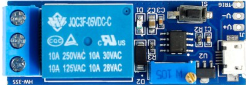
A relay module is an electronic device that acts as a switch, which can be controlled by a low-power signal to turn on or off a separate high-power circuit. The 5V-30V relay module is designed to operate within a voltage range of 5 volts to 30 volts, making it versatile for various applications. Common use cases include home automation, industrial controls, and automotive electronics, where it is necessary to control devices like motors, lights, and other high-power loads with a microcontroller or logic signal.

Explore Projects Built with Relay module 5v-30v

Use Cirkit Designer to design, explore, and prototype these projects online. Some projects support real-time simulation. Click "Open Project" to start designing instantly!
DC-DC Converter and Relay Module Power Distribution System
Image of relay: A project utilizing Relay module 5v-30v in a practical application
This circuit consists of a DC-DC converter powering a 6-channel power module, which in turn supplies 5V to a 2-relay module. The power module distributes the converted voltage to the relay module, enabling it to control external devices.
Cirkit Designer LogoOpen Project in Cirkit Designer
ESP32-Controlled Relay Module for Smart Switch Applications
Image of DCN: A project utilizing Relay module 5v-30v in a practical application
This circuit consists of an ESP32 microcontroller connected to a relay module. The ESP32's GPIO pin D13 is used to trigger the relay, allowing the microcontroller to control higher power devices. The relay module is powered by the ESP32's 3.3V output, and the ground is shared between the two components.
Cirkit Designer LogoOpen Project in Cirkit Designer
ESP32C3-Based Smart AC Light Controller with Voltage Sensing
Image of plugins: A project utilizing Relay module 5v-30v in a practical application
This circuit appears to be a smart AC power control system. The XIAO ESP32C3 microcontroller is used to monitor AC voltage through the ZMPT101B module and to control a 12v Relay, which in turn switches an AC Bulb on or off. The Mini AC-DC module provides the 5V power required by the microcontroller and the relay, while the AC Wire provides the AC power to the system.
Cirkit Designer LogoOpen Project in Cirkit Designer
ESP32 Wi-Fi Controlled Dual Relay Module
Image of esp: A project utilizing Relay module 5v-30v in a practical application
This circuit features an ESP32 microcontroller connected to a two-channel 5V relay module. The ESP32 controls the relay channels via its GPIO pins D23 and D22, allowing it to switch external devices on and off. The relay module is powered by the 3.3V and GND pins of the ESP32.
Cirkit Designer LogoOpen Project in Cirkit Designer

Explore Projects Built with Relay module 5v-30v

Use Cirkit Designer to design, explore, and prototype these projects online. Some projects support real-time simulation. Click "Open Project" to start designing instantly!
Image of relay: A project utilizing Relay module 5v-30v in a practical application
DC-DC Converter and Relay Module Power Distribution System
This circuit consists of a DC-DC converter powering a 6-channel power module, which in turn supplies 5V to a 2-relay module. The power module distributes the converted voltage to the relay module, enabling it to control external devices.
Cirkit Designer LogoOpen Project in Cirkit Designer
Image of DCN: A project utilizing Relay module 5v-30v in a practical application
ESP32-Controlled Relay Module for Smart Switch Applications
This circuit consists of an ESP32 microcontroller connected to a relay module. The ESP32's GPIO pin D13 is used to trigger the relay, allowing the microcontroller to control higher power devices. The relay module is powered by the ESP32's 3.3V output, and the ground is shared between the two components.
Cirkit Designer LogoOpen Project in Cirkit Designer
Image of plugins: A project utilizing Relay module 5v-30v in a practical application
ESP32C3-Based Smart AC Light Controller with Voltage Sensing
This circuit appears to be a smart AC power control system. The XIAO ESP32C3 microcontroller is used to monitor AC voltage through the ZMPT101B module and to control a 12v Relay, which in turn switches an AC Bulb on or off. The Mini AC-DC module provides the 5V power required by the microcontroller and the relay, while the AC Wire provides the AC power to the system.
Cirkit Designer LogoOpen Project in Cirkit Designer
Image of esp: A project utilizing Relay module 5v-30v in a practical application
ESP32 Wi-Fi Controlled Dual Relay Module
This circuit features an ESP32 microcontroller connected to a two-channel 5V relay module. The ESP32 controls the relay channels via its GPIO pins D23 and D22, allowing it to switch external devices on and off. The relay module is powered by the 3.3V and GND pins of the ESP32.
Cirkit Designer LogoOpen Project in Cirkit Designer

Technical Specifications

Key Technical Details

  • Operating Voltage: 5V to 30V DC
  • Control Signal Voltage: Typically 3.3V or 5V (compatible with most microcontrollers like Arduino)
  • Maximum Switching Voltage: Up to 250V AC or 30V DC
  • Maximum Switching Current: Up to 10A (depending on the relay rating)
  • Contact Type: SPDT (Single Pole Double Throw)
  • Relay Type: Electromechanical

Pin Configuration and Descriptions

Pin Name Description
VCC Connect to the positive supply voltage (5V-30V)
GND Connect to the ground of the power supply
IN Control signal input from microcontroller
NO Normally Open contact, closes when relay is activated
COM Common contact, connect to the circuit you want to control
NC Normally Closed contact, opens when relay is activated

Usage Instructions

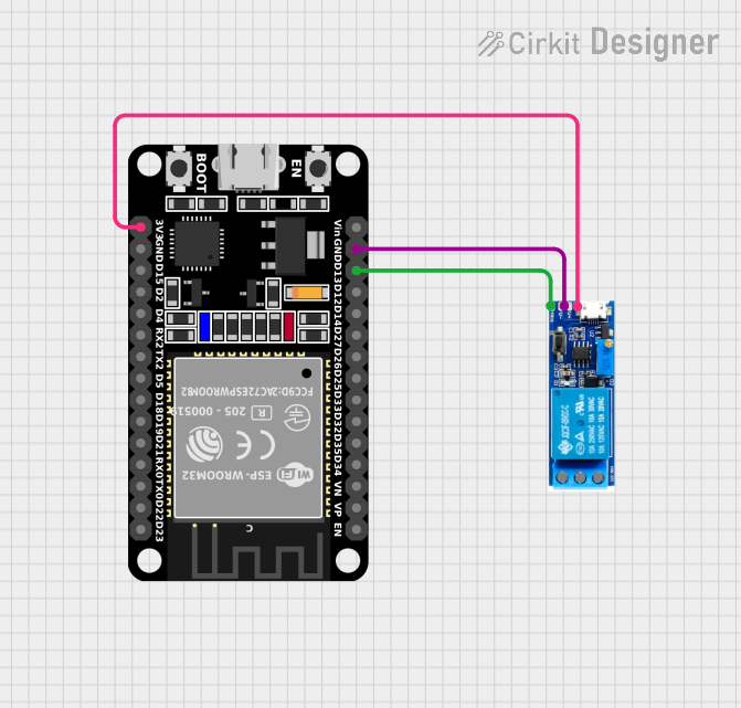
How to Use the Relay Module in a Circuit

  1. Connect the VCC pin to a positive power supply within the 5V-30V range.
  2. Connect the GND pin to the ground of the power supply.
  3. Connect the IN pin to a digital output pin of a microcontroller.
  4. Connect the device you want to control between the COM pin and either the NO or NC pin, depending on whether you want the device to be on or off when the relay is not powered.

Important Considerations and Best Practices

  • Ensure that the power supply voltage does not exceed the specified maximum voltage of the relay module.
  • Do not exceed the maximum switching current and voltage ratings to avoid damaging the relay and the controlled device.
  • Use a flyback diode across inductive loads to prevent voltage spikes when turning off the relay.
  • Consider using a separate power supply for the relay module if the controlled device requires a lot of power.

Example Code for Arduino UNO

// Define the relay control pin
const int relayPin = 7;

void setup() {
  // Set the relay control pin as an output
  pinMode(relayPin, OUTPUT);
}

void loop() {
  // Turn on the relay (connects COM and NO, disconnects NC)
  digitalWrite(relayPin, HIGH);
  delay(1000); // Wait for 1 second
  
  // Turn off the relay (disconnects COM and NO, connects NC)
  digitalWrite(relayPin, LOW);
  delay(1000); // Wait for 1 second
}

Troubleshooting and FAQs

Common Issues

  • Relay does not switch: Check the control signal and power supply connections. Ensure the control signal has the correct voltage level.
  • Intermittent operation: Verify that the power supply is stable and within the specified voltage range.
  • Clicking sound but no action: This could indicate a faulty relay or an issue with the load. Check the load does not exceed the relay's ratings.

Solutions and Tips for Troubleshooting

  • Always double-check wiring, especially the power supply and control signal connections.
  • Test the relay module with a multimeter to ensure it is functioning correctly.
  • If using inductive loads, ensure a flyback diode is in place to protect the relay and control circuitry.

FAQs

Q: Can I control this relay module with a 3.3V microcontroller? A: Yes, most 5V relay modules can be triggered with a 3.3V signal, but it's important to check the specific module's datasheet.

Q: Is it safe to switch AC loads with this relay? A: Yes, as long as the AC voltage and current do not exceed the relay's maximum ratings.

Q: How can I increase the number of devices controlled by the relay? A: You can use multiple relay modules or opt for a relay board with multiple channels.

Remember to always follow safety precautions when working with high voltage and current to prevent accidents and equipment damage.