How to Use R6FG RECEIVER: Examples, Pinouts, and Specs
Introduction
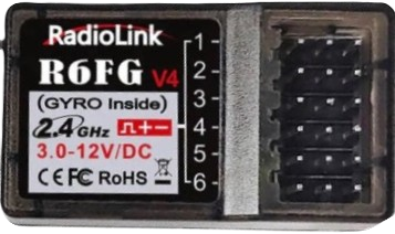
The R6FG Receiver by Radiolink is a compact, high-performance radio frequency receiver designed for remote control applications. It supports multiple channels and ensures reliable communication with compatible transmitters. This receiver is widely used in RC cars, boats, and drones due to its robust signal stability and ease of integration.
Explore Projects Built with R6FG RECEIVER


Explore Projects Built with R6FG RECEIVER
Common Applications and Use Cases
- Remote-controlled cars, boats, and drones
- Robotics and automation systems
- Wireless communication in hobbyist projects
- Model aircraft and other RC vehicles
Technical Specifications
The R6FG Receiver is designed to deliver reliable performance in a variety of environments. Below are its key technical details:
General Specifications
| Parameter | Value |
|---|---|
| Manufacturer | Radiolink |
| Model | R6FG |
| Frequency Range | 2.4 GHz ISM band |
| Channels | 6 |
| Operating Voltage | 4.8V - 10V |
| Signal Output | PWM (Pulse Width Modulation) |
| Range | Up to 600 meters (open field) |
| Dimensions | 35mm x 20mm x 13mm |
| Weight | 6 grams |
Pin Configuration and Descriptions
The R6FG Receiver features a set of pins for connecting to servos, ESCs, and other components. Below is the pin configuration:
| Pin Number | Label | Description |
|---|---|---|
| 1 | CH1 | Channel 1 PWM signal output |
| 2 | CH2 | Channel 2 PWM signal output |
| 3 | CH3 | Channel 3 PWM signal output |
| 4 | CH4 | Channel 4 PWM signal output |
| 5 | CH5 | Channel 5 PWM signal output |
| 6 | CH6 | Channel 6 PWM signal output |
| 7 | BIND | Binding button for pairing with transmitter |
| 8 | VCC | Power input (4.8V - 10V) |
| 9 | GND | Ground connection |
Usage Instructions
How to Use the R6FG Receiver in a Circuit
- Power Connection: Connect the VCC pin to a power source (4.8V - 10V) and the GND pin to ground.
- Servo/ESC Connections: Attach servos or ESCs to the appropriate channel pins (CH1 to CH6) based on your application.
- Binding the Receiver:
- Press and hold the BIND button on the receiver.
- Power on the receiver while holding the button.
- Turn on the transmitter in binding mode.
- Wait for the receiver's LED to indicate a successful bind (steady light).
- Signal Testing: Test the channels by moving the transmitter controls and observing the response of connected devices.
Important Considerations and Best Practices
- Ensure the receiver is powered within the specified voltage range to avoid damage.
- Keep the receiver antenna away from metal parts to maintain signal strength.
- Perform a range test before operating in the field to ensure reliable communication.
- Avoid operating multiple transmitters on the same frequency to prevent interference.
Example: Connecting to an Arduino UNO
The R6FG Receiver can be used with an Arduino UNO to read PWM signals. Below is an example code snippet:
// Example code to read PWM signals from the R6FG Receiver using Arduino UNO
// Connect CH1 of the receiver to pin 2 of the Arduino UNO

const int receiverPin = 2; // Pin connected to CH1 of the receiver
volatile unsigned long pulseStart = 0;
volatile unsigned long pulseWidth = 0;

void setup() {
  pinMode(receiverPin, INPUT); // Set the receiver pin as input
  Serial.begin(9600);          // Initialize serial communication
  attachInterrupt(digitalPinToInterrupt(receiverPin), readPulse, CHANGE);
}

void loop() {
  // Print the pulse width (PWM signal) to the Serial Monitor
  Serial.print("Pulse Width: ");
  Serial.print(pulseWidth);
  Serial.println(" microseconds");
  delay(100); // Delay for readability
}

void readPulse() {
  if (digitalRead(receiverPin) == HIGH) {
    // Record the start time of the pulse
    pulseStart = micros();
  } else {
    // Calculate the pulse width when the signal goes LOW
    pulseWidth = micros() - pulseStart;
  }
}
Notes:
- Ensure the receiver is properly bound to the transmitter before testing.
- Use a common ground between the receiver and Arduino for accurate signal reading.
Troubleshooting and FAQs
Common Issues and Solutions
Receiver Not Binding to Transmitter:
- Ensure the transmitter is in binding mode.
- Check that the receiver is powered correctly.
- Move the transmitter closer to the receiver during binding.
No Signal Output:
- Verify the receiver is bound to the transmitter (steady LED light).
- Check the connections to the servos or ESCs.
- Ensure the transmitter is powered on and configured correctly.
Intermittent Signal Loss:
- Check for interference from other 2.4 GHz devices.
- Ensure the antenna is not obstructed or damaged.
- Perform a range test to confirm signal strength.
Receiver Overheating:
- Verify the input voltage is within the specified range (4.8V - 10V).
- Avoid placing the receiver near heat-generating components.
FAQs
Q: Can the R6FG Receiver be used with any transmitter?
A: The R6FG Receiver is compatible with Radiolink transmitters and may not work with other brands.
Q: What is the maximum range of the R6FG Receiver?
A: The receiver has a maximum range of up to 600 meters in an open field.
Q: How many devices can be connected to the receiver?
A: The receiver supports up to 6 channels, allowing for 6 devices (e.g., servos or ESCs) to be connected.
Q: Can I use the R6FG Receiver for drones?
A: Yes, the R6FG Receiver is suitable for drones, RC cars, boats, and other remote-controlled devices.
Q: What should I do if the receiver's LED keeps blinking?
A: A blinking LED indicates the receiver is not bound to a transmitter. Follow the binding procedure to resolve this issue.